Novel new energy charging pile device

A charging pile and new energy technology, which is applied in the field of new new energy charging pile devices, can solve the problems of inconvenient installation and disassembly process, large damage to the charging pile body, large electric shock risk, etc. The effect of disassembly and assembly efficiency

Inactive Publication Date: 2018-06-29
余储
View PDF0 Cites 0 Cited by
  • Summary
  • Abstract
  • Description
  • Claims
  • Application Information

AI Technical Summary

Problems solved by technology

[0002] Charging pile is an important supporting facility for new energy vehicles. It is mainly used for charging new energy vehicles. Due to its large size, the existing new energy charging piles are extremely inconvenient during installation and disassembly. Moreover, fasteners such as bolts are used The fixed method will cause great damage to the body of the charging pile and has relatively large defects. In addition, the current connection operation of the charging pile after the fixed installation relies on manual operation, which is difficult to operate and has a greater risk of electric shock

Method used


Image

  • Novel new energy charging pile device
  • Novel new energy charging pile device
  • Novel new energy charging pile device

Examples


Embodiment Construction

[0023] All features disclosed in this specification, or steps in all methods or processes disclosed, may be combined in any manner, except for mutually exclusive features and / or steps.

[0024] Any feature disclosed in this specification (including any appended claims, abstract and drawings), unless expressly stated otherwise, may be replaced by alternative features which are equivalent or serve a similar purpose. That is, unless expressly stated otherwise, each feature is one example only of a series of equivalent or similar features.

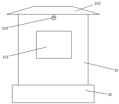
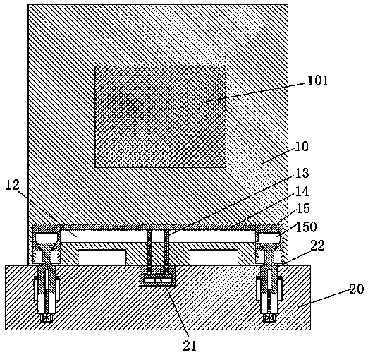
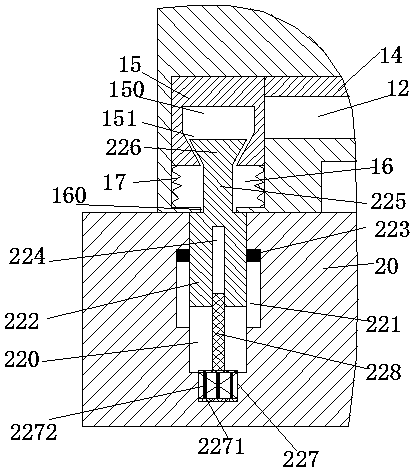
[0025] Such as Figure 1-4 As shown, a new type of new energy charging pile device of the present invention includes a fixing base 20 and a charging pile body 10 installed on the fixing base 20, and a charging end 101 is provided in the middle of the front end of the charging pile body 10. , the top of the charging pile body 10 is fixed with a rain shelter 102, and the bottom end surface of the front side of the rain shelter 102 is provided w...


PUM


Abstract

The invention discloses a novel new energy charging pile device which includes a fixed seat and a charging pile mounted on the fixed seat. A charging end is arranged in the middle of the front end face of the charging pile. A canopy is fixed on the top of the charging pile. The bottom end face of the front side of the rain shelter is provided with a monitoring probe at the upper part of the charging end part. The bottom surface of the charging pile body is symmetrically provided with an empty groove for the fork arm of the forklift. The bottom surface of the charging pile body is symmetricallyprovided with a first sliding cavity. A connecting groove is arranged between two sliding cavities. A first sliding cavity is provided with a first sliding block, the first sliding block is providedwith a ladder groove which is communicated with the back and forth and the port is downwards. The upper end of the ladder groove is provided with an adjusting groove. The bottom wall of the first sliding cavity is provided with a tightening groove connected with the outer end. Two ends of the connecting plate are fixedly connected with the two first sliding blocks and a mounting platform is fixedly arranged at the middle of the connecting plate.

Description

technical field [0001] The invention relates to the field of new energy vehicles, in particular to a novel new energy charging pile device. Background technique [0002] Charging pile is an important supporting facility for new energy vehicles. It is mainly used for charging new energy vehicles. Due to its large size, the existing new energy charging piles are extremely inconvenient during installation and disassembly. Moreover, fasteners such as bolts are used The fixed method has great damage to the body of the charging pile and has relatively large defects. In addition, the current connection operation of the charging pile after the fixed installation relies on manual operation, which is difficult to operate and has a greater risk of electric shock. Contents of the invention [0003] The purpose of the present invention is to provide a new type of new energy charging pile device, which can overcome the above-mentioned defects of the prior art. [0004] According to the...

Claims


Application Information

Patent Timeline
Patent Type & Authority Applications(China)
IPC IPC(8): B60L11/18
CPCB60L53/31Y02T10/70Y02T10/7072Y02T90/12
Inventor 余储
Owner 余储
Why Eureka
Try Eureka