Improved paper shredder

A paper shredder and improved technology, applied in grain processing and other directions, can solve the problems of large occupied area, raised dust particles, complicated setting mode, etc., and achieve the effect of convenient operation and simple structure.

Inactive Publication Date: 2018-06-29
广州鸣博科技有限公司
View PDF4 Cites 1 Cited by
  • Summary
  • Abstract
  • Description
  • Claims
  • Application Information

AI Technical Summary

Problems solved by technology

[0002] At present, paper shredders are often used in some office places for shredding operations. However, the traditional shredder setting mode is relatively complicated and the function is relatively single. It can only perform a single shredding operation, which makes the shredded paper extremely fluffy. In addition, when the traditional paper shredder is shredding paper, because there are many dust particles attached to the paper, it is easy to cause the dust particles to rise and cause serious pollution to the surrounding air.

Method used


Image

  • Improved paper shredder
  • Improved paper shredder

Examples


Embodiment Construction

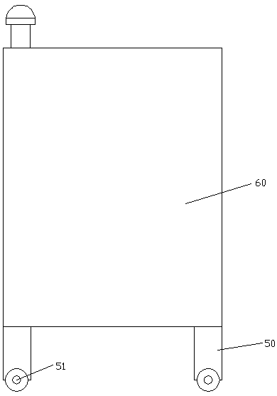
[0014] Such as Figure 1-2 As shown, an improved paper shredder of the present invention includes a pillar 50 and a machine body 60 fixedly arranged on the above. Cutting cavity 622, the inner wall of the body 60 on the right side of the cutting cavity 622 is extended with a first rotating groove 612 up and down, and a first rotating shaft 614 and a second rotating shaft 617 are respectively extending left and right in the cutting cavity 622 The extended tail ends on the right side of the first rotating shaft 614 and the second rotating shaft 617 protrude into the first rotating groove 612 and the tail ends are connected with the first rotating groove 612 in rotation, and the left side of the first rotating shaft 614 The extended tail end is connected with the first driver 645, the outer surface of the first driver is fixed in the inner wall on the left side of the cutting chamber 622, and the left side extension tail end of the second rotating shaft 617 is connected to the le...


PUM


Abstract

The invention discloses an improved paper shredder which includes a support column and a machine body fixedly arranged thereon. Rolling wheels are rollably arranged on the bottom of the support column. A cutting cavity is di sposed in the top end surface of the machine body. A first rotary trough is arranged inside the inner wall, at the right side of the cutting cavity, of the machine body in a vertically extending manner. A first rotary shaft and a second rotary shaft are respectively arranged inside the cutting cavity in a left-and-right extending manner. The right extending tails of the first rotary shaft and the second rotary shaft can enter the first rotary shaft and are in rotational fitting connection therewith. The left extending tail of the first rotary shaft is fitted with and connected to a first driving motor. The outer surface of the first driving motor is fixedly arranged in the left inner wall of the cutting cavity. The left extending tail of the second rotary shaft isin rotational fitting connection with the left inner wall of the cutting cavity. Spiral blades are circumferentially fixed to the outer surfaces of the first rotary shaft and the second rotary shaft in the cutting cavity.

Description

technical field [0001] The invention relates to the technical field of paper shredders, in particular to an improved paper shredder. Background technique [0002] At present, paper shredders are often used in some office places for shredding operations. However, the traditional shredder setting mode is relatively complicated and the function is relatively single. It can only perform a single shredding operation, which makes the shredded paper extremely fluffy. In addition, when the traditional paper shredder is shredding paper, there are many dust particles attached to the paper, it is easy to cause the dust particles to rise up, causing serious pollution to the surrounding air. Contents of the invention [0003] The technical problem to be solved by the present invention is to provide an improved paper shredder, which can solve the above-mentioned problems in the prior art. [0004] The present invention is achieved through the following technical solutions: An improved ...

Claims


Application Information

Patent Timeline
Patent Type & Authority Applications(China)
IPC IPC(8): B02C18/14B02C18/24B02C23/20B02C18/16
CPCB02C18/0007B02C18/142B02C18/16B02C18/24B02C23/20B02C2018/0061
Inventor 欧阳翎
Owner 广州鸣博科技有限公司
Why Eureka
Try Eureka