
Novel radiotherapy positioning marking and auxiliary treatment placement device machine and method thereof

A technology for positioning marking and auxiliary treatment, applied in the field of medical devices, can solve problems such as easy confusion, inconvenient movement, and life-long marking, and achieve the effects of reducing foreign body sensation on the body surface, facilitating radiotherapy positioning, and improving positioning speed.

Active Publication Date: 2018-06-29
SHANGHAI PULMONARY HOSPITAL
View PDF7 Cites 0 Cited by
  • Summary
  • Abstract
  • Description
  • Claims
  • Application Information

AI Technical Summary

Problems solved by technology

[0004] At present, there are disadvantages in positioning and positioning: 1) At present, the commonly used body surface marking of patients is to use paint pens to draw on the patient's skin surface, and the disadvantage is that the color is easy to smudge clothes; The markings are easy to fade, and the marking line of the patient often disappears or the marking line becomes thicker (1cm, the normal laser line is only about 1mm). At present, there are also a few units in the market that use tattoo devices to mark points on the patient's skin. The disadvantage is that the mark exists for life. Many patients find it difficult to accept, and some patients need to adjust the positioning point in the later stage, so the tattoo positioning point marked for the first time cannot be removed, and it is easy to be confused in the follow-up treatment
2) When the patient is positioned for treatment, the therapist needs to repeatedly adjust the position of the patient on the bed so that the position of the body marking line is consistent with the position of the marking scale of the bed frame during positioning, and many elderly patients or patients with limited mobility are inconvenient to move; The position of the patient and the treatment bed is manually adjusted, and the positioning process is greatly affected by the supervisor of the technician
[0008] However, there is no report about a novel radiotherapy positioning marker of the present invention and a device machine and method for adjuvant treatment positioning.

Method used


Image

  • Novel radiotherapy positioning marking and auxiliary treatment placement device machine and method thereof
  • Novel radiotherapy positioning marking and auxiliary treatment placement device machine and method thereof
  • Novel radiotherapy positioning marking and auxiliary treatment placement device machine and method thereof

Examples


Embodiment 1

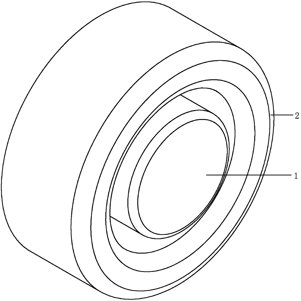
[0047] Please refer to the attached figure 1 , with figure 1 It is a structural schematic diagram of a device, machine and method for a new type of radiotherapy positioning marker and adjuvant treatment positioning in this embodiment. The device machine and method for the novel radiotherapy positioning marker and auxiliary treatment positioning include a body surface marking device (1) and a marker positioning treatment positioning device (2);

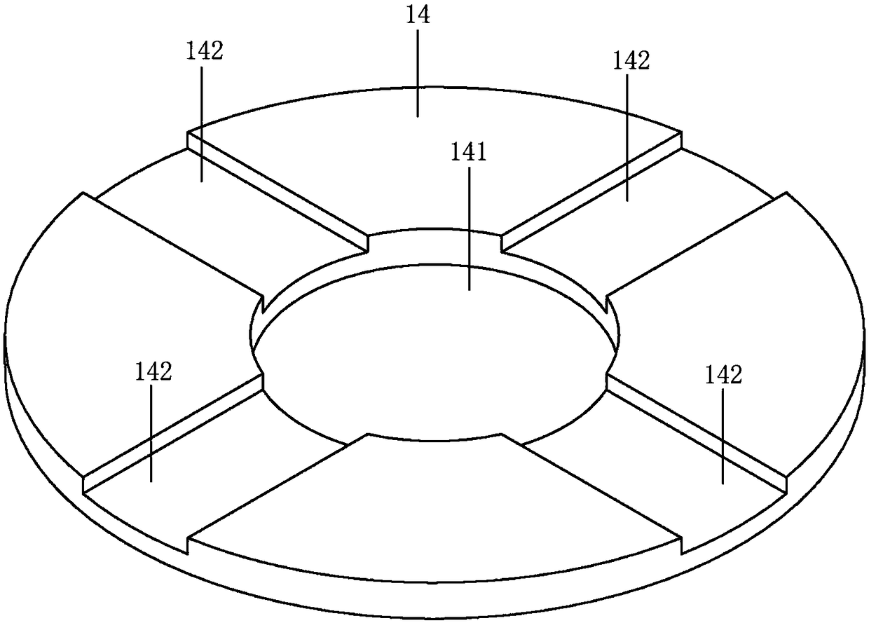
[0048] Please refer to the attached figure 2 , attached image 3 , attached Figure 4 , with figure 2It is a schematic diagram of the combination of a new type of radiotherapy positioning marker and auxiliary treatment positioning device machine and its method, a hollow cone, and a fixed plate in this embodiment; image 3 It is a schematic diagram of the structure of a new type of radiotherapy positioning mark and auxiliary treatment positioning device machine and its method of the cross positioning plate in this embodiment; F...

Embodiment 2

[0057] Please refer to attached figure 1 , attached Figure 6 , with figure 1 , 6 It is a structural schematic diagram of a device, machine and method for a new type of radiotherapy positioning marker and adjuvant treatment positioning in this embodiment.

[0058] Both the lower edge and the upper edge of the body surface marking device (1) have rounded corners to reduce the possible damage of the device to the patient's body surface; the shell fixing hole (111) on the side of the marking shell (11) is used for Place one end of the strap. The groove width of the cross fixing groove (142) on the upper end surface of the cross positioning disc (14) is 2mm, which is used for alignment of the laser line and for combining with the marker positioning treatment positioning device (2) during positioning; the hollow cone (12 ) is used to combine with the marker positioning treatment positioning device (2); the distance between the apex of the hollow cone (12) and the body surface m...

Embodiment approach

[0063] When the body surface marking device (1) and the marking positioning treatment positioning device (2) are not usually removed, they are only removed when the patient's body surface is clear. CBCT verification should be done for each combination.

[0064] When the body surface marking device (1) and the marking positioning treatment positioning device (2) are removed at ordinary times, they are combined only during the treatment positioning, and are removed after positioning.


PUM


Abstract

The invention relates to a novel radiotherapy positioning marking and auxiliary treatment placement device machine and a method thereof. The machine comprises a body surface marking device and a marking positioning treatment placement device, wherein the body surface marking device comprises a marking casing, a hollow cone, two fixed plates and a cross positioning plate; the inside of the markingcasing is fixedly connected with the hollow cone and the two fixed plates, two casing fixing holes are formed in the side surface, and the cross positioning plate is connected with an upper end edge opening; the marking positioning treatment placement device comprises a marking positioning casing, a cross fixing pin and a solid cone. The machine has the advantages as follows: accuracy of radiotherapy positioning can be improved from original 2 mm to 0.5 mm; accuracy of radiotherapy placement is improved; placement is semi-intelligent, and the placement speed of technicians is improved; a patient can clean the skin normally, and foreign body sensation on the body surface is reduced; radiotherapy positioning beads can be replaced, and radiotherapy positioning is convenient; other image examinations are not affected; a light sensation circuit technology in radiation ionization and radiation radio frequency environments can be established.

Description

technical field [0001] The invention relates to the technical field of medical devices, in particular to a novel radiotherapy positioning mark and a device for positioning auxiliary treatment and its method. Background technique [0002] Positioning is a process in which the doctor adjusts the position between the patient and the treatment bed and the spatial position of the treatment bed to make the position of each treatment consistent with the positioning during each radiotherapy. It is an important part of radiotherapy. [0003] At present, the positioning steps used in radiotherapy are: 1) the patient is lying on a fixed bed frame during positioning; 2) the film is buckled to fix the position of the patient and the bed frame; 3) imaging scans are performed on the patient; Mark the treatment center point on the membrane body; 5) Remove the membrane body, and trace the position of the patient and the fixed bed frame on the patient's body surface; 6) During each treatment,...

Claims


Application Information

Patent Timeline
IPC IPC(8): A61N5/00
CPCA61N5/00
Inventor 叶影胡忞仁
Owner SHANGHAI PULMONARY HOSPITAL
Learn More