
Flowerpot with drought-proof and waterlogging-proof structure

A waterlogging and drought prevention technology, applied in container cultivation, horticulture, botanical equipment and methods, etc., can solve the problems affecting the normal growth of potted plants, limitations of applicability and practicability, and water supply of potted plants, so as to improve the prevention and control Improve drought performance, improve waterlogging performance, and ensure the effect of water supply demand

Pending Publication Date: 2018-06-29
江荣峰
View PDF9 Cites 0 Cited by
  • Summary
  • Abstract
  • Description
  • Claims
  • Application Information

AI Technical Summary

Problems solved by technology

[0002] A flower pot is a structure used to plant potted plants. The flower pots in the prior art are mainly composed of a pot body and a drainage hole on the bottom wall of the pot body. Although it can meet the general use requirements, in actual use During the process, due to the drainage holes on the bottom wall, the water will be quickly discharged when watering, so it is difficult to provide water for potted plants for a long time, and frequent watering is required, and the drought resistance is relatively limited. When the holes are not opened, watering is easy to accumulate, which will affect the normal growth of potted plants, and the waterlogging performance is poor, so the applicability and practicality are limited

Method used


Image

  • Flowerpot with drought-proof and waterlogging-proof structure
  • Flowerpot with drought-proof and waterlogging-proof structure

Examples


Embodiment 1

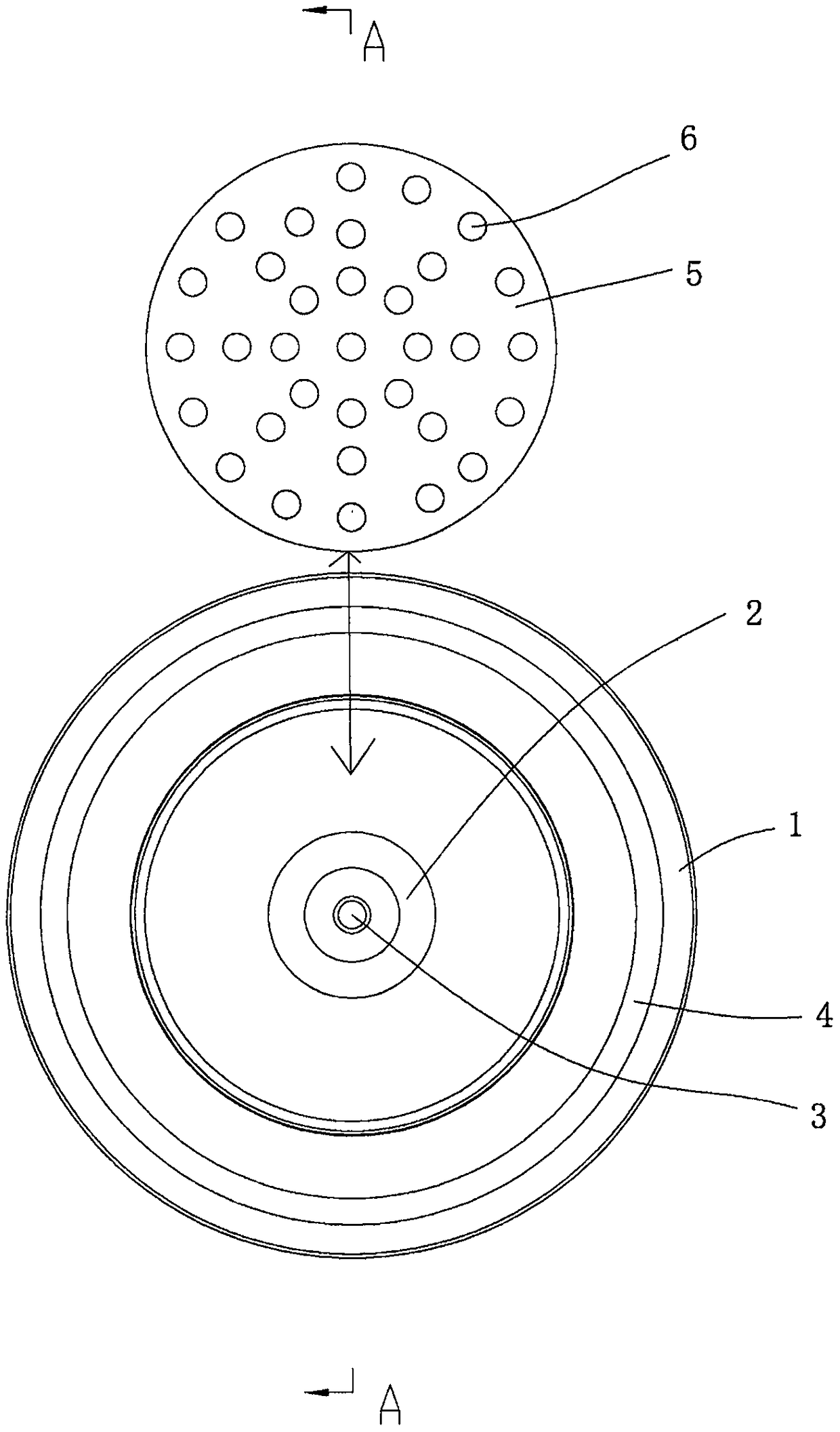
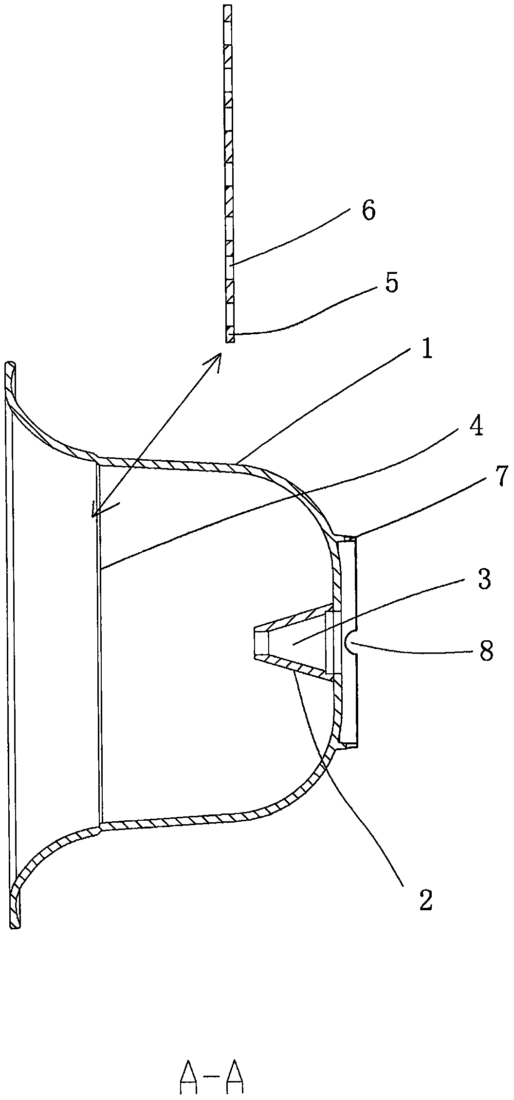
[0013] figure 1 and figure 2 A specific embodiment of the invention is shown in which figure 1 It is a structural schematic diagram of the present invention; figure 2 for figure 1 A-A sectional view in .

[0014] See figure 1 and figure 2 , a flower pot with a drought and waterlogging structure, comprising a pot body 1, a frustum-shaped convex post 2 is fixed at the center of the bottom wall of the pot body 1, and a vertical Drainage hole 3, the bottom end of described drainage hole 3 penetrates the bottom wall of basin body 1 downwards, and the middle part of the inner wall of described basin body 1 is fixed with snap ring 4, and the top end of described frustum-shaped convex post 2 is in Below the clamping convex ring 4, a potted plant carrying partition 5 is also arranged in the pot body 1, on which the potted plant carrying partition 5 is uniformly provided with up and down transparent water-conducting through holes 6, and the potted plant carries The diameter of...


PUM


Abstract

The invention discloses a flowerpot with a drought-proof and waterlogging-proof structure. The flowerpot comprises a pot body, wherein the center of the bottom wall of the pot body is fixedly providedwith a round table type convex column, the center of the round table type convex column is fixedly provided with a vertical drainage hole, the bottom end of the drainage hole penetrates downwards through the bottom wall of the pot body, the middle portion of the inner wall of the pot body is fixedly provided with a clamping convex ring, the top end of the round table type convex column is locatedunder the clamping convex ring, the pot body is further internally provided with a potting bearing partition plate, the potting bearing partition plate is uniformly provided with hollow water-conducting through holes, the diameter of the potting bearing partition plate is larger than that of the clamping convex ring and smaller than that of a pot body cavity, and the edge of the potting bearing partition plate abuts against the top surface of the clamping convex ring. The flowerpot with the drought-proof and waterlogging-proof structure has the advantages that the structure arrangement is reasonable, the bottom wall of the flowerpot is provided with the round table type convex column, a certain amount of water can be stored in the pot body, so that the drought-proof performance is greatlyimproved, the potting bearing partition plate is also provided, so that the potted plant can be prevented from being immersed for a long time, thereby greatly improving the drought-proof performance,and the practicality is high.

Description

technical field [0001] The invention belongs to the technical field of potting equipment, and in particular relates to a flowerpot with a structure for preventing drought and waterlogging. Background technique [0002] A flower pot is a structure used to plant potted plants. The flower pots in the prior art are mainly composed of a pot body and a drainage hole on the bottom wall of the pot body. Although it can meet the general use requirements, in actual use During the process, due to the drainage holes on the bottom wall, the water will be quickly discharged when watering, so it is difficult to provide water for potted plants for a long time, and frequent watering is required, and the drought resistance is relatively limited. When the holes are not opened, watering is easy to accumulate, which will affect the normal growth of potted plants, and the waterlogging performance is poor, so the applicability and practicability are limited. Contents of the invention [0003] T...

Claims


Application Information

Patent Timeline
Patent Type & Authority Applications(China)
IPC IPC(8): A01G9/02A01G27/06
CPCA01G9/028A01G27/06
Inventor 江荣峰
Owner 江荣峰
Learn More