Magnetic detecting device of intelligent electric permanent magnetic chuck

An electric permanent magnet chuck and magnetic force detection technology, applied in the direction of electromagnet, permanent magnet, magnetic performance measurement, etc., can solve the problem of not knowing whether there is a problem with the die hole, not being able to judge whether there is magnetic generation, and inability to judge the magnitude of the magnetic force, etc. To achieve the effect of saving mold replacement and adjustment time, convenient operation, and concentrated magnetic force

Pending Publication Date: 2018-06-26
佛山市顺德区盛锵德磁科技有限公司
View PDF0 Cites 0 Cited by
  • Summary
  • Abstract
  • Description
  • Claims
  • Application Information

AI Technical Summary

Problems solved by technology

[0002] 1. The old electro-permanent magnetic sucker installs a large mold hole on the front or back of the mold, and several single magnetic groups are arranged in the mold hole, and then filled with resin, and then covered with a cover plate to waterproof , anti-deviation and other functions, the magnetic interference between the magnets of several single magnetic components placed in this large mold pit is too large, the suction force of the suction cup is weakened, and the forward transmission of the magnetic force is affected; 2. The old electropermanent magnetic chuck has no magnetic force detection coil. It is impossible to judge whether there is magnetism, the magnitude of the magnetic force cannot be judged, and it is impossible to know whether there is a problem with the die hole. It can only be judged by experience or tested one by one to detect faults; at the same time, it also increases the occurrence of safety accidents

Method used


Image

  • Magnetic detecting device of intelligent electric permanent magnetic chuck
  • Magnetic detecting device of intelligent electric permanent magnetic chuck
  • Magnetic detecting device of intelligent electric permanent magnetic chuck

Examples


Embodiment Construction

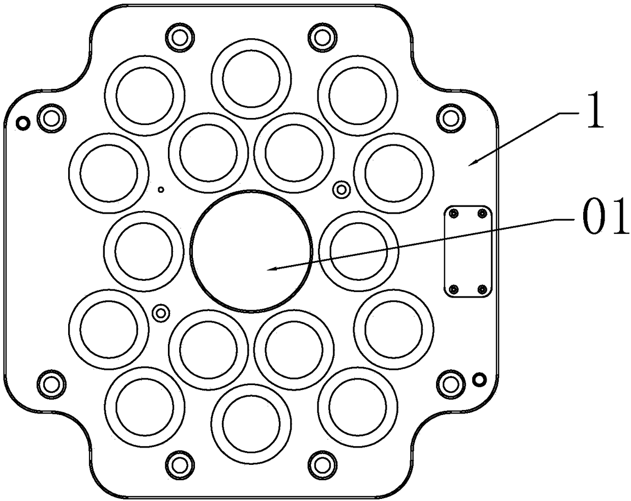
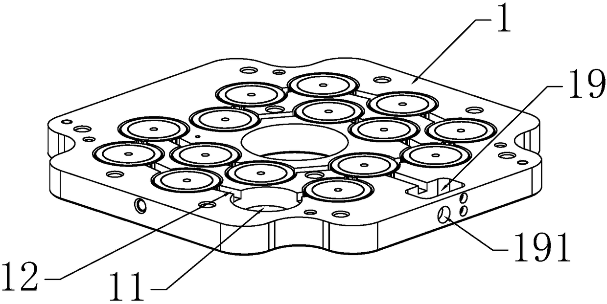
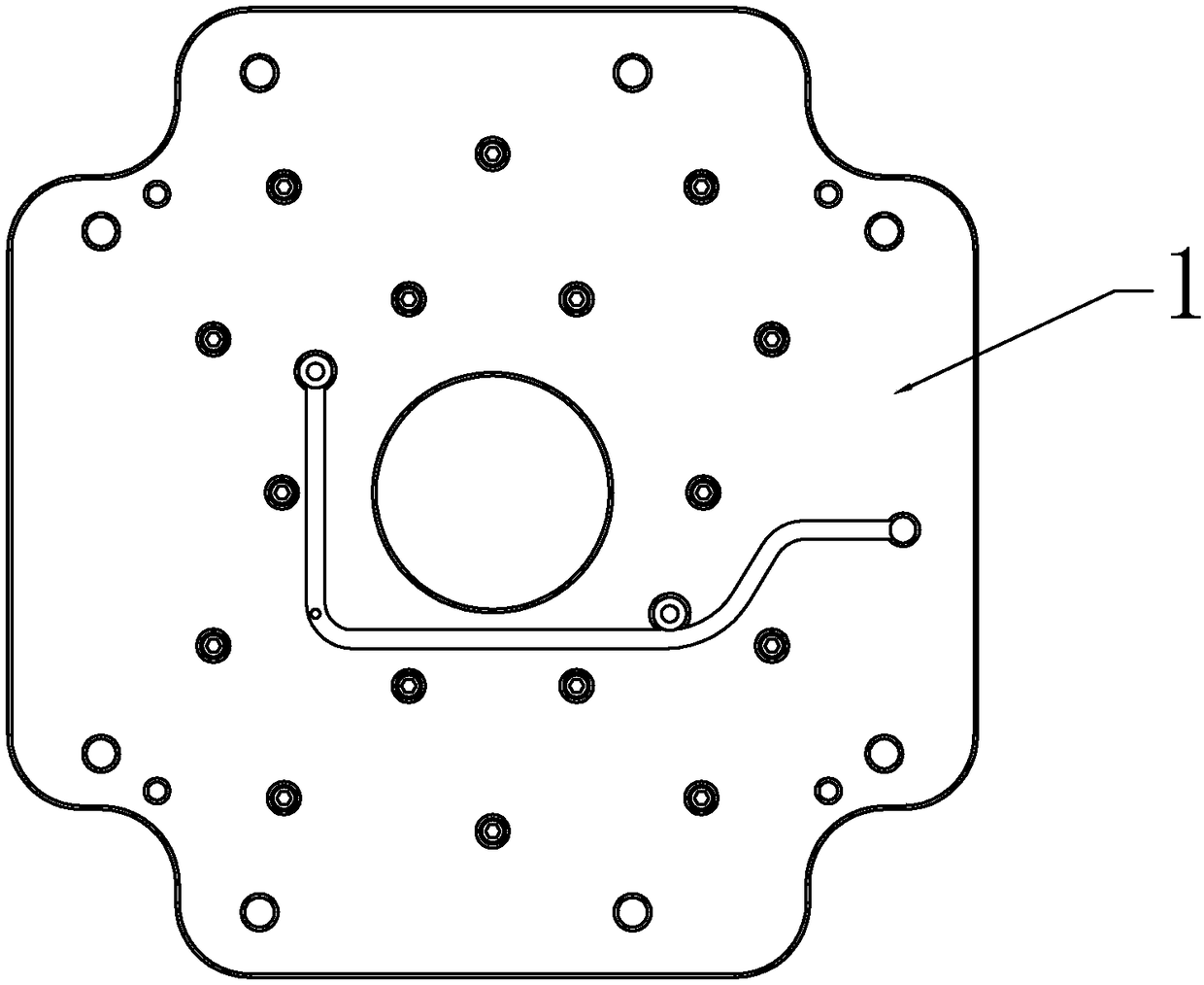
[0025] A magnetic detection device for an intelligent electric permanent magnetic chuck, the magnetic detection device includes a template 1, the reverse side of the template 1 is provided with several blind holes 11, lead gaps 12 are arranged between the blind holes 11, and each blind hole 11 The bottom is provided with a magnetic detection coil 2, and a magnetic force generating device 3 is fixed above the magnetic detection coil 2; a cover plate 4 is provided on the reverse side of the template 1, and the cover plate 4 is connected and fixed to the template 1 by screws and will be located in the blind hole 11 The magnetic force generating device 3 of mouth is compressed.

[0026] The magnetic force generating device 3 includes a cylinder 31 integrally connected with the template 1 protruding from the middle of the blind mold hole 11, and a surrounding groove 32 surrounding the cylinder 31 is formed between the cylinder 31 and the mold wall of the blind mold hole 11, and the ...


PUM


Abstract

The present invention discloses a magnetic detection device of an intelligent electric permanent magnetic chuck. The magnetic detection device includes a template, a plurality of blind die holes are arranged in the back side of the template, lead gaps are arranged among the blind die holes, a magnetic detection coil is arranged on the bottom of each blind die hole, a magnetic generation device isfixed on the top of the magnetic detection coil, the back face of the template is provided with a cover plate which is fixedly connected with the template via a screw and tightly presses the magneticgeneration device on the opening of the blind die hole. The invention aims to calculate the magnetic force generated by each die hole and gather the magnetic force, the magnetic force is converted into the magnetic attraction force, and the magnitude of the magnetic force can be known in real time on a liquid crystal display of a controller after conversion, and at the same time, whether the template is completely magnetically attracted with an attracted object can be judged via the magnitude of the magnetic force, the operation is simple, and the safety accidents are reduced.

Description

technical field [0001] The invention relates to the field of magnetic suction devices, in particular to a magnetic detection device for an intelligent electric permanent magnetic chuck. Background technique [0002] 1. The old electro-permanent magnetic sucker installs a large mold hole on the front or back of the mold, and several single magnetic groups are arranged in the mold hole, and then filled with resin, and then covered with a cover plate to waterproof , anti-deviation and other functions, the magnetic interference between the magnets of several single magnetic components placed in this large mold pit is too large, the suction force of the suction cup is weakened, and the forward transmission of the magnetic force is affected; 2. The old electropermanent magnetic chuck has no magnetic force detection coil. It is impossible to judge whether there is magnetism, the magnitude of the magnetic force cannot be judged, and it is impossible to know whether there is a proble...

Claims


Application Information

Patent Timeline
IPC IPC(8): H01F7/02H01F7/20G01R33/12
CPCH01F7/0252G01R33/12H01F7/206H01F2007/208
Inventor 李锵华方刘文
Owner 佛山市顺德区盛锵德磁科技有限公司
Why Eureka
Try Eureka