Gas testing device and testing method based on inflated constant pressure in sealing cavity
A test device, constant pressure device technology, applied in the direction of measuring devices, suspension and porous material analysis, instruments, etc., can solve problems such as incompatibility, achieve good sealing, simple sealing method, and convenient data collection
Pending Publication Date: 2018-06-22
CHINA UNIV OF MINING & TECH (BEIJING)
View PDF0 Cites 0 Cited by
- Summary
- Abstract
- Description
- Claims
- Application Information
AI Technical Summary
Problems solved by technology
In the actual production process, a large factor affecting the porosity of coal is the pressure on the coal body from the overlying strata, but in the similar simulation process in th
Method used
View moreImage
Smart ImageViewing Examples
Examples
 PUM
 Abstract
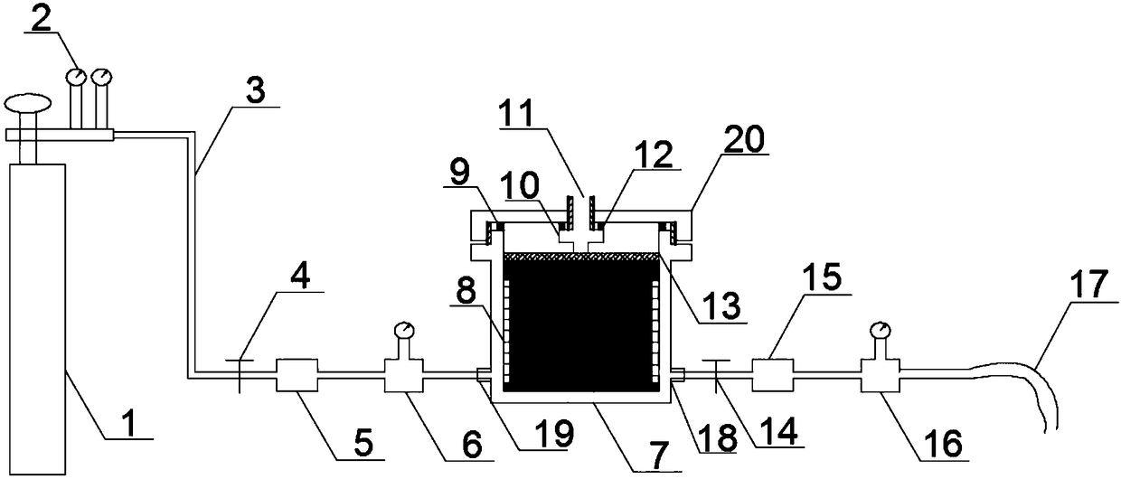
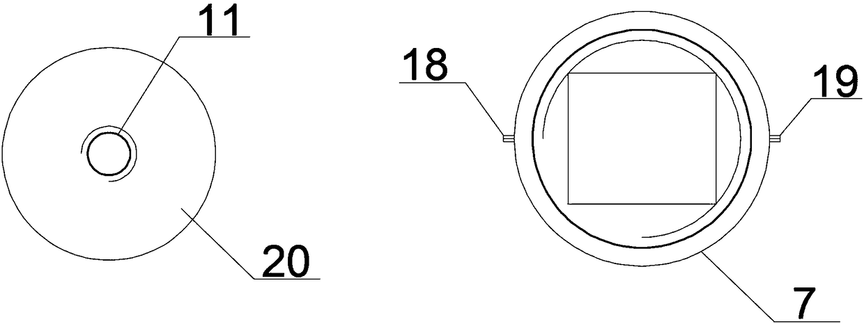
The invention discloses a gas testing device and testing method based on inflated constant pressure in a cavity. Equipment comprises a sealing main body frame, an intra-cavity constant pressure inflating device, a gas supply and control system, a gas traffic dynamic monitoring system and a data collecting computer; the main body frame is mainly composed of a cylindrical cavity, an air inlet, an air outlet, a sealing cover, and an O-shaped sealing rubber ring; the sealing cover and the sealing cavity are in threaded connection; the gas supply and control system is located at the left side of the sealing main body frame; the gas traffic dynamic monitoring system and the data collecting computer are located at the right side of the sealing main body frame; a rigid jack part and the sealing cover are in threaded connection so as to control the pressure size through the amount of the injected hydraulic oil; the sealing main body frame, the gas supply and control system and the gas traffic dynamic monitoring system are connected through a gas pipeline. Through the testing device and method disclosed by the invention, the good and emulational test research equipment is provided for adjusting the pressure size above the media in the analog simulation process according to the actual overlying rock situation.
Description
technical field [0001] The invention relates to a gas test device and a test method for applying constant pressure in a sealed cavity Background technique [0002] The gas permeability of the coal seam has a significant impact on the gas occurrence state and flow characteristics in the coal body, and the porosity in the coal body and its surrounding rock has an important influence on the gas permeability of the coal seam. The porosity of coal body not only affects the adsorption and desorption of gas by coal, but also affects the channels of gas flow in coal micropores. In the actual production process, a large factor affecting the porosity of coal is the pressure on the coal body from the overlying strata, but in the similar simulation process in the laboratory, the pressure on the coal mass from the overlying strata is mostly ignored. Due to the influence of volume porosity, the simulated results do not match the actual ones. Therefore, in the similar simulation process ...
Claims
Login to View More Application Information
Patent Timeline
 IPC IPC(8): G01N15/08
CPCG01N15/0826
Inventor 赵洪宝黄轶凡张欢王宏冰
Owner CHINA UNIV OF MINING & TECH (BEIJING)
Features
- Generate Ideas
- Intellectual Property
- Life Sciences
- Materials
- Tech Scout
- Unparalleled Data Quality
- Higher Quality Content
- 60% Fewer Hallucinations
Learn More Browse by: Latest US Patents, China's latest patents, Technical Efficacy Thesaurus, Application Domain, Technology Topic, Popular Technical Reports.
© 2025 PatSnap. All rights reserved.Legal|Privacy policy|Modern Slavery Act Transparency Statement|Sitemap|About US| Contact US: help@patsnap.com


