
Electronic imager-based distance measuring method and system

A technology of electronic imaging and ranging method, applied in the field of ranging, can solve the problems of cumbersome operation, difficult to distinguish buttons, poor user experience, etc.

Inactive Publication Date: 2018-06-22
INFIRAY TECH CO LTD
View PDF8 Cites 0 Cited by
  • Summary
  • Abstract
  • Description
  • Claims
  • Application Information

AI Technical Summary

Problems solved by technology

The operation of the entire ranging process is cumbersome, and it is necessary to operate different buttons on the electronic imager multiple times. The user experience is not good, especially when operating at night, the various buttons are not easy to distinguish, and it is easy to cause misuse.

Method used


Image

  • Electronic imager-based distance measuring method and system
  • Electronic imager-based distance measuring method and system
  • Electronic imager-based distance measuring method and system

Examples


Embodiment Construction

[0028] The following will clearly and completely describe the technical solutions in the embodiments of the present invention with reference to the accompanying drawings in the embodiments of the present invention. Obviously, the described embodiments are only some, not all, embodiments of the present invention. Based on the embodiments of the present invention, all other embodiments obtained by persons of ordinary skill in the art without making creative efforts belong to the protection scope of the present invention.

[0029] Please refer to figure 2 , figure 2 It is a schematic diagram of the principle of ranging by an electronic imager in a specific implementation manner provided by the present invention.

[0030] In a specific embodiment provided by the present invention, the distance measuring method based on the electronic imager mainly includes three steps. In the first step, a clear target image is first obtained through the electronic imager, and at the same time,...


PUM


Abstract

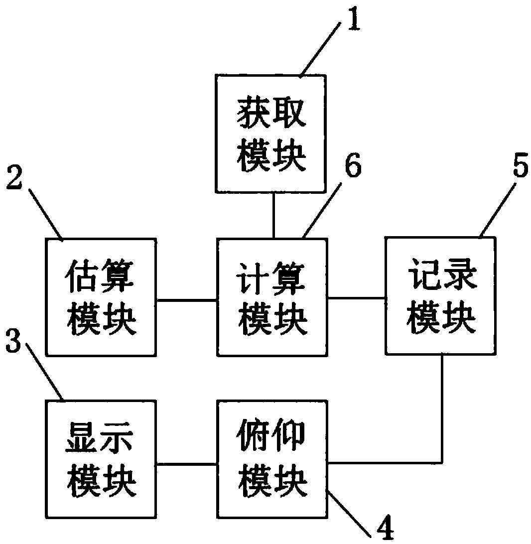
The invention discloses an electronic imager-based distance measuring method. The electronic imager-based distance measuring method comprises the following steps: acquiring a target image and the focal length through an electronic imager, and estimating the height dimension of the target according to a preset ratio; displaying a horizontal reticle associated with an electronic compass in an imaging screen of the electronic imager, sequentially moving the horizontal reticle to the highest point and the lowest point of the target image, and recording the angle change amount of the electronic compass when the horizontal reticle is moved from the highest point to the lowest point of the target image; calculating a target distance according to a formula that x is equal to C2*cotalpha, wherein C2 is the height dimension of the target and alpha is the angle change amount of the electronic compass. By the electronic imager-based distance measuring method, distance measuring operation through the electronic imager is simplified, and only through movement of the horizontal reticle and recording of the angle change amount through the electronic compass, the distance measuring operation on thetarget is simply and conveniently achieved, so that a user experience is improved. The invention further discloses an electronic imager-based distance measuring system. The electronic imager-based distance measuring system has the former beneficial effects.

Description

technical field [0001] The invention relates to the technical field of ranging, in particular to a ranging method based on an electronic imager. The invention also relates to a ranging system based on an electronic imager. Background technique [0002] There are many types of electronic imagers, including cameras, video cameras, video recorders, scanners, etc. In some cases, electronic imagers can also be used for ranging. [0003] At present, the existing electronic imaging products can judge the target distance by the number of pixels (px) of the target in the image and the focal length and pixel size of the product. The principle is as follows: figure 1 shown. The ratio of the target height size to the target distance is equal to the ratio of the product of the pixel size and the number of pixels occupied by the target image to the focal length, that is, C 2 / x=p q / C 1 , where C 1 is the focal length, C 2 is the target height, p is the number of pixels occupied by ...

Claims


Application Information

Patent Timeline
Patent Type & Authority Applications(China)
IPC IPC(8): G01C3/00
CPCG01C3/00
Inventor 黄星明孙同波
Owner INFIRAY TECH CO LTD
Learn More