
Platform crane collision prevention system and method

A crane and anti-collision technology, which is applied in the direction of cranes, load hanging components, transportation and packaging, etc., can solve the problems of high investment cost, increase of sensors, and existence of blind spots, and achieve optimized anti-collision function, simple maintenance and debugging, and stable performance reliable effect

Pending Publication Date: 2018-06-22
SHANGHAI ZHENHUA HEAVY IND
View PDF6 Cites 9 Cited by
  • Summary
  • Abstract
  • Description
  • Claims
  • Application Information

AI Technical Summary

Problems solved by technology

But at the same time, it also increases the hardware and construction costs in the early stage and the maintenance workload in the future.
Therefore, the sensor detection method cannot be perfectly transplanted and applied to the offshore platform. It is necessary to adopt a comprehensive dynamic position detection algorithm and protection measures to realize and optimize the anti-collision function of the crane on the offshore platform.
[0004] In addition, there are also studies that use GPS to collect position information, and perform anti-collision protection after calculation and processing. The disadvantage of this method is that it needs to maintain good satellite signals for a long time to ensure the accuracy of anti-collision position calculation, and ordinary GPS cannot accurately respond to height information. The height change of the collision object cannot be effectively identified, so it can only be used as anti-collision protection on the plane
In addition, the additional cost of system interface and hardware and debugging services is also a factor to be considered by the GPS method
[0005] Therefore, existing technologies exist: single point-to-point or point-to-surface anti-collision protection will have blind spots; increasing the number of sensors will increase the hardware and construction costs in the early stage and the maintenance workload in the future; Satellite signals to ensure the accuracy of collision avoidance position calculation, and there are technical problems that GPS cannot respond to height information and high investment costs

Method used


Image

  • Platform crane collision prevention system and method
  • Platform crane collision prevention system and method
  • Platform crane collision prevention system and method

Examples


Embodiment Construction

[0050] The implementation of the present invention will be illustrated by specific specific examples below, and those skilled in the art can easily understand other advantages and effects of the present invention from the content disclosed in this specification. Although the description of the present invention will be presented in conjunction with a preferred embodiment, it does not mean that the features of the invention are limited to this embodiment. On the contrary, the purpose of introducing the invention in conjunction with the embodiments is to cover other options or modifications that may be extended based on the claims of the present invention. The following description contains numerous specific details in order to provide a thorough understanding of the present invention. The invention may also be practiced without these details. Also, some specific details will be omitted from the description in order to avoid obscuring or obscuring the gist of the present invent...


PUM


Abstract

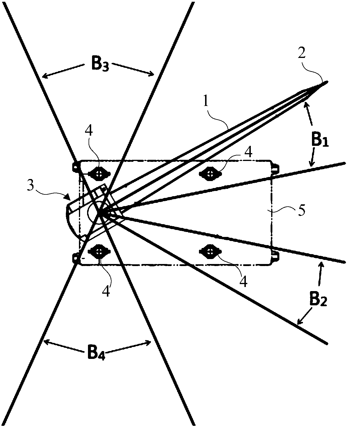
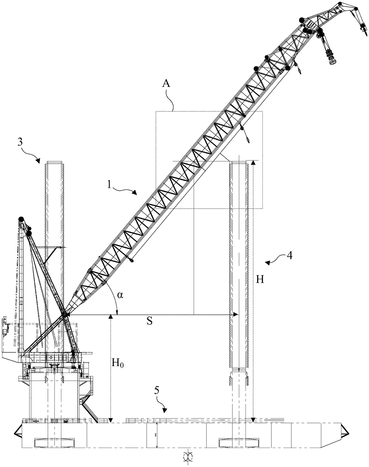
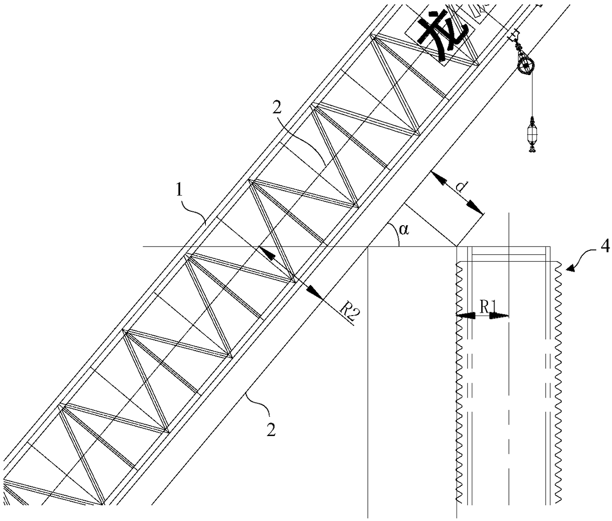
The invention provides a platform crane collision prevention system and method. The platform crane collision prevention system includes a collection device and a control device; the collection deviceis used for collecting position information of a cantilever of a crane and position information of an obstacle on a platform; the control device is in communication connection with the collection device and is used for obtaining relative position relations between the obstacle and the cantilever according to the position information and structure information of the obstacle and the position information and structure information of the cantilever, and according to the position relations, alarm signals, signals for controlling the cantilever to stop moving downwards or signals for controlling the crane to stop rotating are given. By the adoption of the platform crane collision prevention system and method, detection limitation of traditional external sensors is broken, and by calculating andjudging the collected position information and structure information of the cantilever of the crane and the collected position information and structure information of the obstacle on the platform, acollision prevention function of the crane on the platform is achieved and optimized; the platform crane collision prevention system and method have the advantages of being low in investment, easy tomaintain and debug and stable and reliable in performance.

Description

technical field [0001] The invention relates to the field of crane control, in particular to a platform crane anti-collision system and an anti-collision method. Background technique [0002] At present, the anti-collision function of cranes is mainly used in the field of onshore tower cranes, and most of them use infrared detection, sound waves or radar electromagnetic wave transceivers to realize point-to-point and point-to-point anti-collision monitoring and protection. [0003] However, since the boom angle, slewing angle, and obstacle height of the platform on the wind power installation platform are all variables, the collision points are spread all over most of the boom and obstacles, and there will be blind spots if a single point-to-point or point-to-surface anti-collision protection is used , has certain limitations. In order to eliminate this limitation, it can be considered to increase the number of sensors, so that the monitoring object approaches the surface (...

Claims


Application Information

Patent Timeline
IPC IPC(8): B66C23/88B66C13/16B66C13/46
CPCB66C13/16B66C13/46B66C23/88
Inventor 沈刚沈柳峰刘险峰孟旭陆忠华查炜烨刘辉秦方玮严竞博
Owner SHANGHAI ZHENHUA HEAVY IND
Learn More