
Servo motor logistics roller

A servo motor and logistics technology, applied in conveyor objects, rollers, conveyors, etc., can solve the problems of uncontrolled, high maintenance cost, and short gear wear life, and achieve simple assembly and manufacturing, convenient follow-up maintenance, The effect of lower production costs

Pending Publication Date: 2018-06-22
常州合泰微特电机有限公司
View PDF0 Cites 4 Cited by
  • Summary
  • Abstract
  • Description
  • Claims
  • Application Information

AI Technical Summary

Problems solved by technology

[0003] 1. The AC motor is equipped with a gearbox-type logistics roller. This kind of logistics roller is relatively large in size and uses high-voltage electricity. It has a relatively high insulation level and only controls the speed of the motor. It is difficult to control the motor torque. The efficiency of the AC motor Low, high energy consumption, high-speed operation cannot be achieved due to the limitation of the gearbox, and the noise of the gearbox is relatively large, and the service life of the gears is not long due to wear and tear
[0004] 2. The brushless motor is equipped with a gearbox-type logistics roller. This type is also divided into two types, one with Hall and one without Hall. This type is small in size and low in cost. Due to the addition of a gearbox, its The maintenance cost is relatively high, the control function is not complete, and it is not the regulation of the actual full speed range. Due to its own structure, when the speed is too high, it will appear out of control, speeding, and noise. At low speed, it is affected by the characteristics of the motor. Relatively large, can not output a large torque, there is no fully closed-loop position signal, let alone achieve precise position control
[0006] However, in the conventional servo motor roller type logistics roller, there is only one shaft that runs through the motor casing and the roller, and the encoder cannot be installed inside the logistics roller. The encoder must be installed in the hollow shaft after the shaft is processed into a hollow shaft. Time-consuming and labor-intensive and increases manufacturing costs

Method used


Image

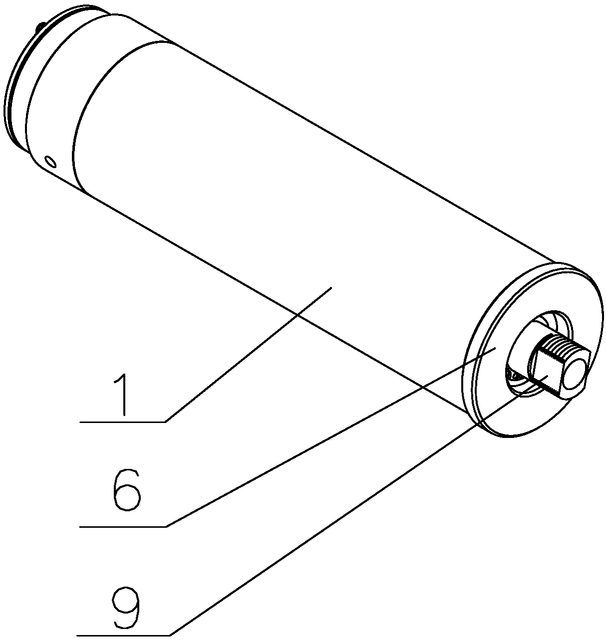
  • Servo motor logistics roller
  • Servo motor logistics roller

Examples


Embodiment Construction

[0015] In order to make the content of the present invention more clearly understood, the present invention will be further described in detail below based on specific embodiments and in conjunction with the accompanying drawings.

[0016] Such as figure 1 , 2 As shown, a servo motor logistics roller includes a drum 1, a motor casing 2, a main shaft 3, a magnetic steel 8 and an iron core 7, the magnetic steel 8 is arranged on the inner wall of the motor casing 2, and the iron core 7 is set on the main shaft 3 And fixedly connected with the main shaft 3, the roller 1 is sleeved on the motor casing 2 and fixedly connected with the motor casing 2 by screws; the front end of the motor casing 2 is connected with a front end cover 4, and the motor casing 2 The rear end is provided with a middle end cover 5, and the rear end of the drum 1 is fixed with a rear end cover 6, and the space between the middle end cover 5 and the rear end cover 6 is used to accommodate an encoder, and the...


PUM


Abstract

The invention discloses a servo motor logistics roller. The servo motor logistics roller comprises a roller, a motor casing, a main shaft, magnetic steel and an iron core, wherein the magnetic steel is arranged on the inner wall of the motor shell, the iron core sleeves the main shaft and is fixedly connected with the main shaft, the roller sleeves the motor shell and is fixedly connected with themotor shell, the front end of the motor shell is connected with a front end cover, a middle end cover is arranged at the rear end of the motor shell, a rear end cover is fixed at the rear end of theroller, the main shaft penetrates through a cavity of the motor shell, the front end of the main shaft is supported on the front end cover through a bearing, the rear end of the main shaft is supported on the middle end cover through a bearing, and an auxiliary shaft is supported on the rear end cover through a bearing. According to the servo motor logistics roller, an encoder can be convenientlyinstalled inside the servo motor logistics roller, so that the servo motor logistics roller is simple in structure, convenient to assemble, and complete in function, and remarkably reduces the cost.

Description

technical field [0001] The invention relates to a logistics roller of a servo motor, which belongs to the technical field of logistics transportation. Background technique [0002] At present, my country's logistics industry is developing rapidly, and motor logistics rollers are needed in the sorting process of goods. Traditional motor logistics rollers can basically be divided into three types: [0003] 1. The AC motor is equipped with a gearbox-type logistics roller. This kind of logistics roller is relatively large in size and uses high-voltage electricity. It has a relatively high insulation level and only controls the speed of the motor. It is difficult to control the motor torque. The efficiency of the AC motor Low power consumption, high energy consumption, high-speed operation cannot be achieved due to the limitation of the gearbox, and the noise of the gearbox is relatively large, and the service life of the gears is not long due to wear and tear. [0004] 2. The b...

Claims


Application Information

Patent Timeline
IPC IPC(8): B65G39/02B65G23/08H02K21/00
CPCH02K21/00B65G23/08B65G39/02
Inventor 赵卫忠马洋陈洪刚
Owner 常州合泰微特电机有限公司
Learn More