Bracket and chair with same
A technology of chairs and brackets, which is applied in the field of brackets and chairs, and can solve problems such as getting out of the backrest and physical fatigue
- Summary
- Abstract
- Description
- Claims
- Application Information
AI Technical Summary
Problems solved by technology
Method used
Image
Examples
Embodiment 1
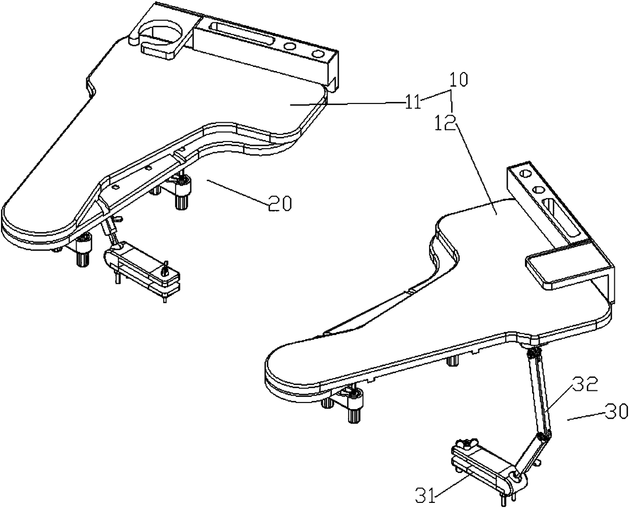
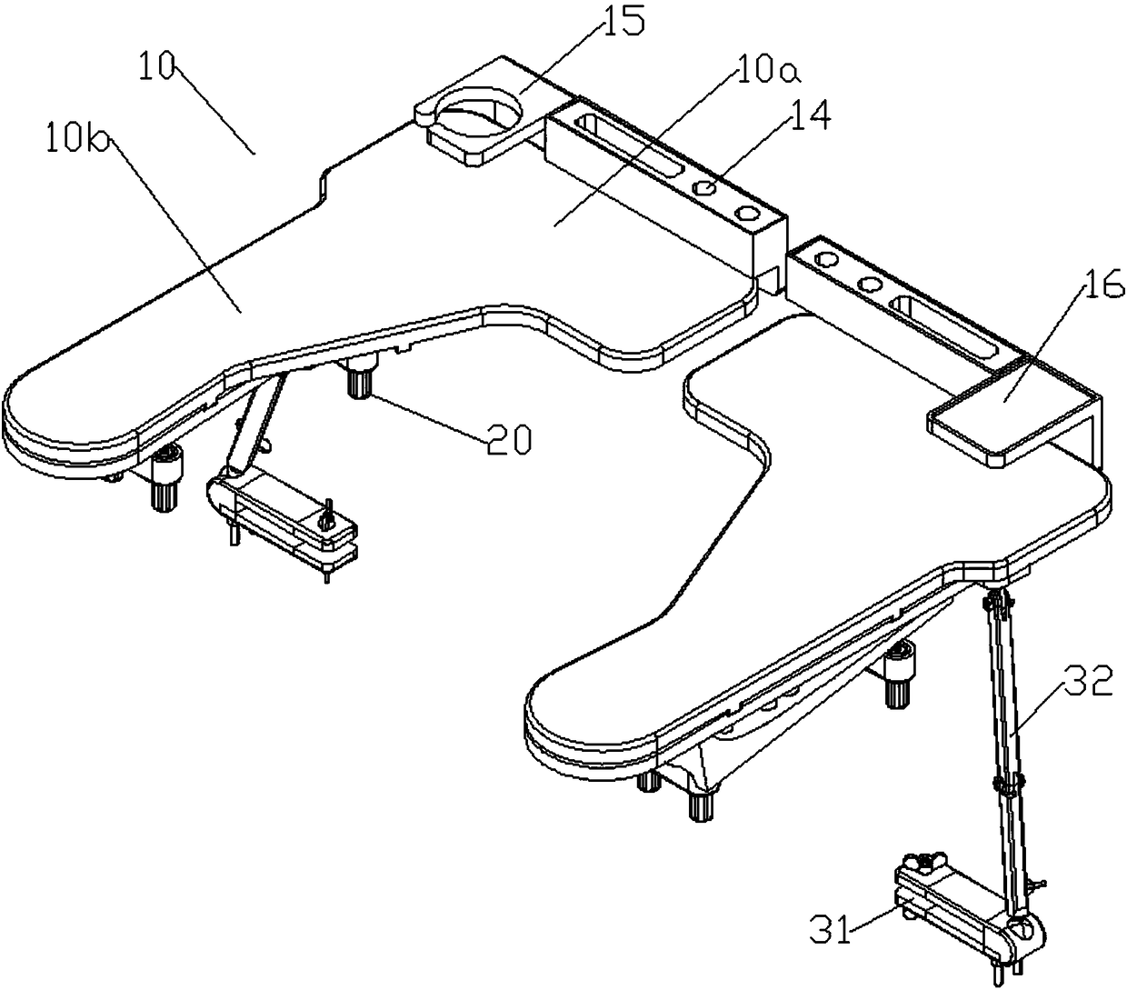
[0101] like Figure 1 to Figure 3 As shown, a bracket provided in this embodiment includes a pallet 10 and a fixing part 20;
[0102] The fixing part 20 is arranged on the bottom of the supporting board 10, and is used to detachably arrange the supporting board 10 on the armrests on the left and right sides of the chair 50;
[0103] The front end of the pallet 10 is provided with a horizontal portion 10a;
[0104] The supporting board 10 includes a left supporting board 11 and a right supporting board 12 respectively arranged on the left and right sides of the chair 50;
[0105] as shown in the picture image 3 As shown, in the state of use, the horizontal portions 10a of the left pallet 11 and the right pallet 12 extend from the left and right sides of the chair 50 to the middle (that is, in front of the chest or in front of the body) and are placed horizontally on the human body. The front side is so that people's left and right hands can naturally stretch out to the fron...
Embodiment 2
[0135] The structure of this embodiment is basically the same as that of Embodiment 1, the difference is that:
[0136] like Figure 5 As shown, the connection structure includes: a first clamping plate 23, a second clamping plate 24, and a compression bolt 25; the first clamping plate 23 and the second clamping plate 24 are vertically arranged at the bottom of the basic connector 21; A clamping space for accommodating chair armrests is provided between the clamping plate 23 and the second clamping plate 24;
[0137] The first clamping plate 23 and the second clamping plate 24 are provided with threaded through holes 24a;
[0138] The hold-down bolt 25 extends into the clamping space from the outside of the chair through the threaded through hole 24a on the second clamping plate 24, and the top of the hold-down bolt leans against the side of the armrest, thereby realizing a fixed connection with the armrest.
[0139] In order to include a handrail, the top of the compression...
Embodiment 3
[0144] The structure of this embodiment is basically the same as that of Embodiment 1, the difference is that:
[0145] like Image 6 As shown, the fixing part 20 is provided with slots 27 at the bottom of the base connector 21 for snapping onto the two side edges of the chair panel of the chair;
[0146] The fixing part 20 is divided into a left fixing part 20a arranged under the left supporting board 11, and a right fixing part 20b arranged under the right supporting board 12;
[0147] The left fixing part 20a and the right fixing part 20b are respectively clamped on the left and right sides of the chair panel through the card slot 27, and the left fixing part 20a and the right fixing part 20b are connected by connecting pieces.
[0148] The connecting piece is an adjustable telescopic rod under the chair panel, and the two ends of the telescopic rod are detachably connected to the left fixing part 20a and the right fixing part 20b respectively.
[0149] The telescopic rod...
PUM
 Abstract
Description
Claims
Application Information
 - Generate Ideas
- Intellectual Property
- Life Sciences
- Materials
- Tech Scout
- Unparalleled Data Quality
- Higher Quality Content
- 60% Fewer Hallucinations
Browse by: Latest US Patents, China's latest patents, Technical Efficacy Thesaurus, Application Domain, Technology Topic, Popular Technical Reports.
© 2025 PatSnap. All rights reserved.Legal|Privacy policy|Modern Slavery Act Transparency Statement|Sitemap|About US| Contact US: help@patsnap.com


