
Automatic vehicle identification and monitoring device with automatic protection mechanism

An automatic identification and automatic protection technology, which is applied in the traffic control system of road vehicles, cleaning methods using tools, supporting machines, etc., can solve the problems that monitoring probes affect the monitoring effect and reduce the efficiency of vehicle entry and exit, and achieve installation, production and operation. Convenience, high practicability, and simple overall structure

Inactive Publication Date: 2018-06-19
JIANGSU YUEHENG INTELLIGENT TECH CO LTD
View PDF0 Cites 6 Cited by
  • Summary
  • Abstract
  • Description
  • Claims
  • Application Information

AI Technical Summary

Problems solved by technology

[0002] The monitoring system is mainly composed of two parts: front-end equipment and back-end equipment. Perform their duties, and establish corresponding links with various equipment in the central control system through wired, wireless or optical fiber transmission media, while the front-end equipment part of the monitoring system, that is, the monitoring probe part, is exposed to the outdoor environment, so it is difficult to detect the location of the monitoring system in the wind and snow. Weather, the front port of the monitoring probe will be easily blocked by rain and snow, which will affect the monitoring effect, especially when the vehicle at the door automatically recognizes the monitoring camera, the strong wind and snow weather will easily affect the recognition effect and reduce the efficiency of vehicle entry and exit

Method used


Image

  • Automatic vehicle identification and monitoring device with automatic protection mechanism
  • Automatic vehicle identification and monitoring device with automatic protection mechanism

Examples


Embodiment Construction

[0016] The following will clearly and completely describe the technical solutions in the embodiments of the present invention. Obviously, the described embodiments are only some of the embodiments of the present invention, rather than all the embodiments. Based on the embodiments of the present invention, all other embodiments obtained by persons of ordinary skill in the art without creative work fall within the protection scope of the present invention:

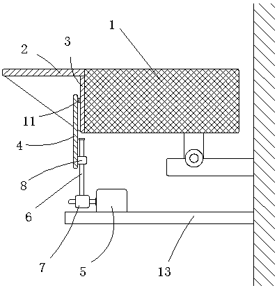
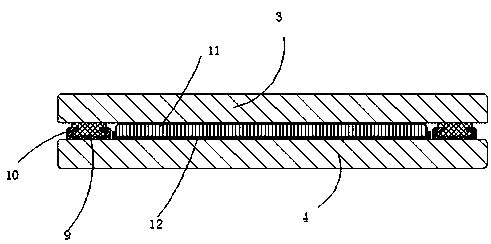
[0017] Such as figure 1 , figure 2 A vehicle automatic identification and monitoring device with an automatic protection mechanism is shown, including a monitoring probe housing 1, a protective cover 2, a transparent protective plate 3, a movable protective plate 4, a drive motor 5, a screw 6, a worm gear mechanism 7 and a fixed Seat 8, the protective cover 2 is fixedly installed on the front side upper part of the monitoring probe housing 1, the transparent protective plate 3 is fixedly installed on the front end of the m...


PUM


Abstract

The invention discloses an automatic vehicle identification and monitoring device with an automatic protection mechanism. The device comprises a monitoring probe shell, a protective cover, a transparent protection plate, a movable protection plate, a driving motor, a screw, a worm gear mechanism and a fixed seat, wherein the protective cover is fixedly installed at the upper part of the front sideof the monitoring probe shell, the transparent protection plate is fixedly installed at the front end of the monitoring probe shell, the movable protection plate is placed outside the transparent protection plate and is arranged in parallel to the transparent protection plate, both sides of the transparent protection plate are provided with sliding rails, the outer middle part of the lower platebody of the movable protection plate is connected with the fixed seat, a threaded hole for the screw to pass through vertically is formed in the fixed seat, the screw is vertically arranged, and the lower end of the screw is connected to the upper end of the worm of the worm gear mechanism. The automatic vehicle identification and monitoring device with the automatic protection mechanism controlsthe motor to drive the protection plates to lift up and down and further plays a role in protecting a front-side baffle, can also play a role in cleaning effectively, and is high in practicability.

Description

technical field [0001] The invention relates to a vehicle automatic identification monitoring device with an automatic protection mechanism, and relates to the technical field of monitoring equipment. Background technique [0002] The monitoring system is mainly composed of two parts: front-end equipment and back-end equipment. Perform its duties, and establish corresponding links with various equipment in the central control system through wired, wireless or optical fiber transmission media, while the front-end equipment part of the monitoring system, that is, the monitoring probe part, is exposed to the outdoor environment, so it is difficult to control the system in a heavy snowstorm. Weather, the front port of the monitoring probe will be easily blocked by rain and snow, which will affect the monitoring effect, especially when the vehicle at the door automatically recognizes the monitoring camera, the strong wind and snow weather will easily affect the recognition effect...

Claims


Application Information

Patent Timeline
IPC IPC(8): H04N5/225B08B1/00F16M13/02G08G1/017H04N7/18
CPCH04N7/18G08G1/0175F16M13/02H04N23/50H04N23/51B08B1/12
Inventor 陆美花王卫星
Owner JIANGSU YUEHENG INTELLIGENT TECH CO LTD
Learn More