
Mobile protection signal intelligent monitoring system

An intelligent monitoring system and protection signal technology, applied in the general control system, control/regulation system, transmission system, etc., can solve the safety of workers' lives and the loss of national property, can not fundamentally avoid accidents, and affect the production order of railway transportation etc. to achieve the effect of reducing the labor intensity of employees, displaying simple and clear results, and reducing the workload of personnel

Pending Publication Date: 2018-06-19
TIANJIN RUIMIN TECH DEV
View PDF0 Cites 1 Cited by
  • Summary
  • Abstract
  • Description
  • Claims
  • Application Information

AI Technical Summary

Problems solved by technology

At present, the installation and removal of the protective signal for loading and unloading operations is managed manually. If the installation is wrong or the removal is not timely, it will easily cause personal casualties or railway traffic accidents, seriously affecting the normal transportation and production order of the railway, and causing major damage to the safety of workers and national property. loss
[0003] In recent years, relevant units across the country have carried out tentative research on the monitoring system of protection signals for railway loading and unloading operations. However, the system has not changed the existing protection signal application mode in principle, and is still highly dependent on human operation. The operation and monitoring links are out of touch. Equipment safety, The withdrawal steps are cumbersome, the reliability of use is poor, and the occurrence of accidents cannot be fundamentally avoided, so it has not been popularized

Method used


Image

  • Mobile protection signal intelligent monitoring system
  • Mobile protection signal intelligent monitoring system
  • Mobile protection signal intelligent monitoring system

Examples


Embodiment Construction

[0024] The present invention will be described in detail below with reference to the accompanying drawings and embodiments.

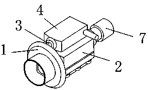
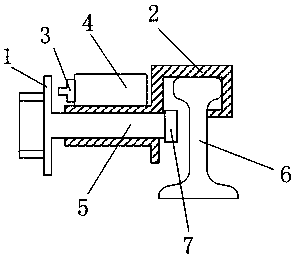
[0025] Such as Figure 1~4 A mobile protection signal intelligent monitoring system is shown, the intelligent monitoring system includes a central control system deployed in the control room and a signal monitoring system deployed at different job sites; the central control system includes a WEB server deployed in the same local area network , a database server, and a plurality of clients; the signal monitoring system includes a signal display box and a detection terminal; the signal display box and the WEB server are interconnected through a wireless network; the signal display box is provided with a monitoring camera, a main controller, a signal The processing module, the GPS positioning module, and the signal indicating box are connected to the detection terminal through a cable; the detection terminal includes a sensor 4 installed on the sensor hold...


PUM


Abstract

The invention discloses a mobile protection signal intelligent monitoring system. The intelligent monitoring system comprises a central control system and multiple signal monitoring systems. The central control system comprises a WEB server and a database server which are arranged in the same local area network and multiple client sides. Each signal monitoring system comprises a detection terminaland a signal representation box which is interconnected with the WEB server through the wireless network. The signal representation box is provided with a monitoring camera, a master controller, a signal processing module and a GPS positioning module. The signal representation box is connected with the detection terminal through a cable. The detection terminal comprises a sensor which is installed on a sensor fixing base. The switch of the sensor is arranged on the side surface of the sensor. A threaded top rod penetrates through the threaded hole arranged in the middle of the sensor fixing base. The top end of the threaded top rod is provided with a pressing disc, and the tail end is provided with a crimping head. The system is high in reliability, convenient to maintain, low in fault rate and convenient and rapid to use so that the personnel workload can be effectively reduced, the production efficiency can be enhanced and thus the system has great social and economic benefits.

Description

technical field [0001] The invention relates to the field of railway loading and unloading equipment, in particular to an intelligent monitoring system for mobile protection signals. Background technique [0002] The protective signal for railway loading and unloading operations is a mobile safety device composed of derailers, signal plates, connecting rods and other related equipment. It is an important safety protection facility in the railway sector. During the loading and unloading operation of the railway, in order to prevent the operation vehicle from being collided by the shunting machine and protect the personal safety of the loading and unloading operators and the safety of the vehicle equipment, a derailer will be installed on the left rail in the direction of the operation vehicle before loading and unloading. After the loading and unloading operation is completed, the protective signal with the derailer is removed. At present, the installation and removal of th...

Claims


Application Information

Patent Timeline
Patent Type & Authority Applications(China)
IPC IPC(8): G05B19/048H04L29/08
CPCH04L67/025G05B19/048
Inventor 王战浩李阳冯晓婷刘伟范思为毕盛
Owner TIANJIN RUIMIN TECH DEV
Learn More