
Chain type automatic transfer printing device

A chain-type, pad printing technology, applied in printing, printing machines, rotary printing machines, etc., can solve the problem of the inability to realize the fully automated process of feeding fixtures, the lack of controllability and stability of the overall process, and the impact on the working efficiency of pad printing machines and other problems, to achieve the effect of solving waste of manpower and material resources, high operation stability, and stable process

Pending Publication Date: 2018-06-19
东莞市铧美电子有限公司
View PDF16 Cites 2 Cited by
  • Summary
  • Abstract
  • Description
  • Claims
  • Application Information

AI Technical Summary

Problems solved by technology

However, the pad printing equipment in the prior art is usually an independent production equipment, which only performs pad printing on the jig with the workpiece installed, and cannot realize the full automation of feeding the jig, loading the workpiece, pad printing and dismantling the finished product. During the production process, the carrier needs to be replaced many times, which affects the working efficiency of the pad printing machine, wastes manpower and material resources, and increases the cost of production; secondly, most of the existing pad printing machine worktables use plane vibration Disc workbenches or shuttle workbenches have defects such as slow running speed, inconvenient operation, and high manufacturing costs, which lead to the lack of controllability and stability of the overall process, and low processing precision, which affects the quality of finished products

Method used


Image

  • Chain type automatic transfer printing device
  • Chain type automatic transfer printing device
  • Chain type automatic transfer printing device

Examples


specific Embodiment 1

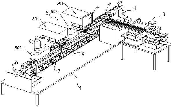
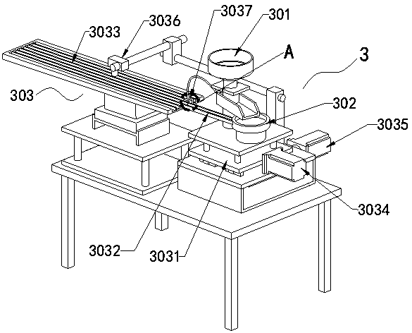
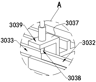
[0023] Specific Example 1: See Figure 1 to Figure 6 , in an embodiment of the present invention, a chain-type automatic pad printing equipment includes a frame 1, a PLC controller 2, a feeding unit 3, a loading unit 4, a pad printing unit 5, a reciprocating sprocket conveying device 7 and a feeding unit Unit 6; the feeding unit 3 and the loading unit 4 are on one side of the frame 1, the pad printing unit 5 is in the middle of the frame 1, and the unloading unit 6 is arranged on the frame The other side of 1; the feeding unit 3 is on the right side of the feeding unit 4, and the feeding unit 3 includes a blanking cylinder 301, a vibrating plate 302 and a multi-track vibrating feeding device 303, and the vibrating plate 302 is set Below the blanking cylinder 301, the multi-track vibrating feeding device 33 is arranged at the discharge port of the vibrating plate 302;

[0024] The reciprocating sprocket conveying device 7 includes a chain 702 and a sprocket 701, the sprocket 7...


PUM


Abstract

The invention discloses a chain type automatic transfer printing device, which comprises a rack, a PLC (Programmable Logic Controller), a feeding unit, a loading unit, a transfer printing unit, a reciprocating type chain wheel conveying device and a discharging unit. The feeding unit and the loading unit are arranged on one side of the rack; the transfer printing unit is arranged in the middle ofthe rack; the discharging unit is arranged on the other side of the rack; the feeding unit is arranged on the right side of the loading unit, and comprises a blanking cylinder, a vibrating plate and amulti-track vibrating and feeding device; the vibrating plate is arranged under the blanking cylinder; and the multi-track vibrating and feeding device is arranged on a discharge hole of the vibrating plate. Compared with the prior art, the chain type automatic transfer printing device provided by the invention realizes full-automatic processes comprising automatically disassembling finished products, automatically feeding jigs, automatically assembling workpieces, automatically transfer printing, and the like, solves the problem that manpower and material resources are wasted, and is beneficial to reducing cost.

Description

technical field [0001] The invention relates to the technical field of pad printing equipment, in particular to a chain type automatic pad printing equipment. Background technique [0002] Pad printing is an indirect intaglio printing technology, which has become the main method for surface printing and decoration of various objects. However, the pad printing equipment in the prior art is usually an independent production equipment, which only performs pad printing on the jig with the workpiece installed, and cannot realize the full automation of feeding the jig, loading the workpiece, pad printing and dismantling the finished product. During the production process, the carrier needs to be replaced many times, which affects the working efficiency of the pad printing machine, wastes manpower and material resources, and increases the cost of production; secondly, most of the existing pad printing machine worktables use plane vibration Disk-type workbenches or shuttle-type wor...

Claims


Application Information

Patent Timeline
Patent Type & Authority Applications(China)
IPC IPC(8): B41F17/00B65G17/12
CPCB65G17/123B41F17/001
Inventor 张立平
Owner 东莞市铧美电子有限公司
Learn More