
Automatic discharge device

The technology of an automatic discharging device and a material blocking device is applied in the field of material processing, which can solve the problems of structure duplication and high equipment cost, and achieve the effect of simple structure and automatic discharging function.

Inactive Publication Date: 2018-06-19
宁波江北文增新材料科技有限公司
View PDF6 Cites 0 Cited by
  • Summary
  • Abstract
  • Description
  • Claims
  • Application Information

AI Technical Summary

Problems solved by technology

In the prior art, after the cutting is completed, manual discharge is mainly considered. Although there is also an automatic discharge device, the structure is too duplicated and the equipment cost is too high

Method used


Image

  • Automatic discharge device

Examples


Embodiment Construction

[0012] The present invention will be described in further detail below by means of specific embodiments:

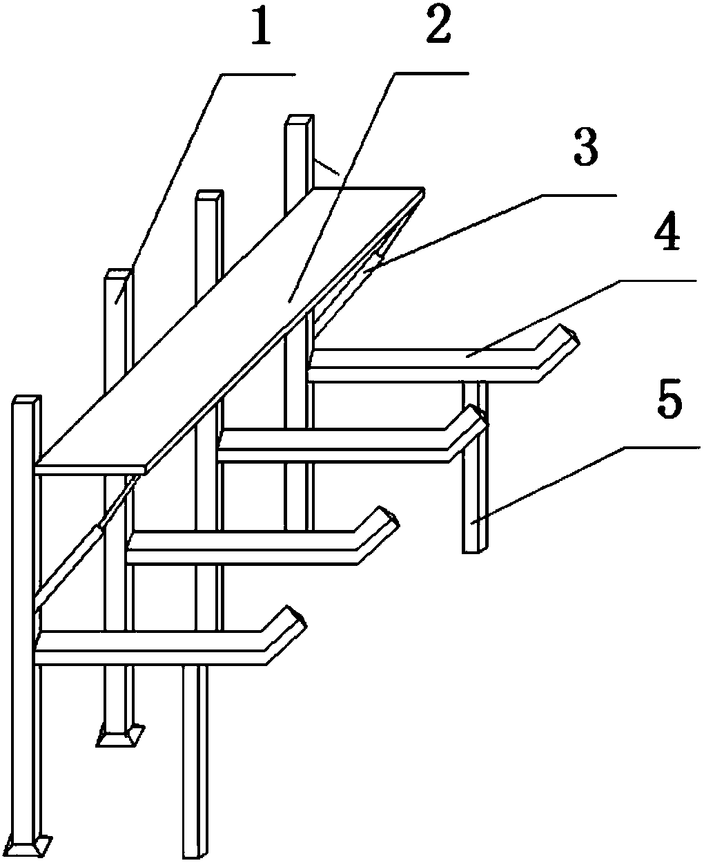
[0013] The reference signs in the accompanying drawings of the description include: bracket 1 , support plate 2 , lifting rod 3 , stopper device 4 , and support rod 5 .

[0014] The embodiment is basically as attached figure 1 Shown: an automatic discharge device, including a bracket 1, a supporting plate 2, a lifting rod 3 and a material blocking device 4, the supporting plate 2 is movably connected with the bracket 1, and the bracket 1 below the supporting plate 2 The lifting rod 3 is fixed on the top, the top of the lifting rod 3 is movably connected with the supporting plate 2, the material blocking device 4 is located below the supporting plate 2, the lifting rod 3 is provided with a pneumatic device, and the lifting rod 3 It forms an angle of 30° with the support 1, and the material retaining device 4 is a metal retaining rod with one end fixed on the support 1, an...


PUM


Abstract

The invention relates to the technical field of material machining, and discloses an automatic discharge device. The automatic discharge device comprises a bracket, a support plate, a lifting rod anda stop device; the support plate is movably connected with the bracket; the lifting rod is aslant upwards fixed on the bracket below the support plate; the top end of the lifting rod is movably connected with the support plate; and the stop device is arranged below the support plate. The automatic discharge device realizes the automatic discharge function through simple structure and low cost, andimproves the working efficiency.

Description

technical field [0001] The invention relates to the technical field of material processing, in particular to an automatic discharging device. Background technique [0002] Board is a general term for boards and squares that are sawn longitudinally from logs. Rectangular wood whose width is more than three times the thickness is called "plank", and rectangular wood whose width is less than three times the thickness is called "square wood". When processing various wood boards, size cutting is required to make them reach standard sizes before they can be packaged and shipped. In the prior art, after the cutting is completed, manual discharge is mainly considered. Although there is also an automatic discharge device, the structure is too duplicated and the equipment cost is too high. Contents of the invention [0003] The purpose of the present invention is to solve the problems existing in the discharge device of the plate automatic cutting machine, and to provide a dischar...

Claims


Application Information

Patent Timeline
Patent Type & Authority Applications(China)
IPC IPC(8): B27C9/00
CPCB27C9/00
Inventor 项文增
Owner 宁波江北文增新材料科技有限公司
Learn More