
Artificial porous barrier model positioning and installation device for wind tunnel test

A positioning and installation, wind tunnel test technology, applied in the direction of measuring device, aerodynamic test, machine/structural component test, etc., can solve the problems of low test efficiency, low adjustment accuracy, complicated operation, etc. Strong, improve test efficiency, flexible control effect

Pending Publication Date: 2018-06-15
JILIN UNIV
View PDF0 Cites 0 Cited by
  • Summary
  • Abstract
  • Description
  • Claims
  • Application Information

AI Technical Summary

Problems solved by technology

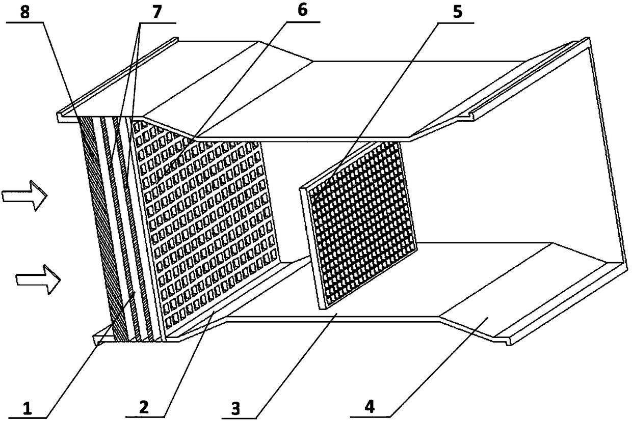
[0005] In the process of studying the dust retention effect of porous barriers in the existing wind tunnel tests, usually the test personnel manually install the artificial porous barrier model in the wind tunnel test system with simple pendants such as sticky hooks, and each time the artificial porous barrier model is adjusted 5 The position of the artificial porous barrier model 5 needs to be manually completed, the operation is more complicated, the specificity is strong, and the positioning and installation effect is poor. The position adjustment of the artificial porous barrier model 5 is not systematic, the adjustment accuracy is not high, and the test efficiency is low.

Method used


Image

  • Artificial porous barrier model positioning and installation device for wind tunnel test
  • Artificial porous barrier model positioning and installation device for wind tunnel test
  • Artificial porous barrier model positioning and installation device for wind tunnel test

Examples


specific Embodiment approach

[0040] In order to further illustrate the beneficial effects brought by the technical solution of the present invention, in conjunction with the accompanying drawings, the specific implementation of the present invention is as follows:

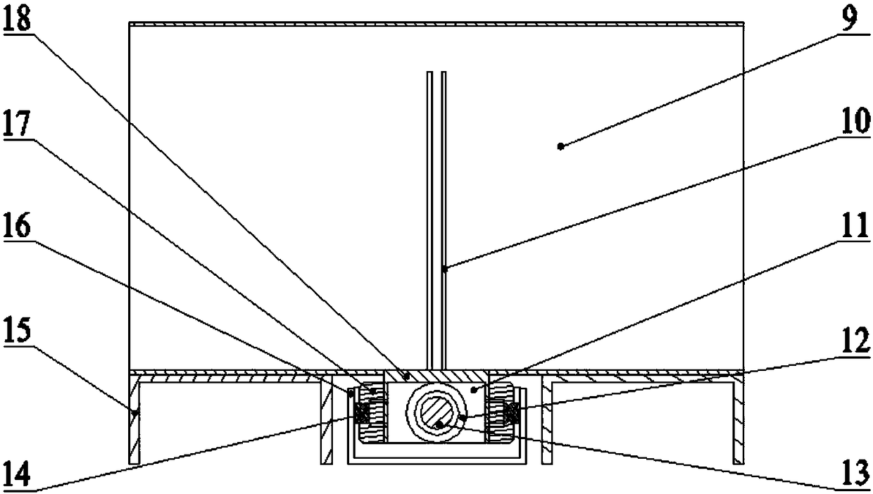
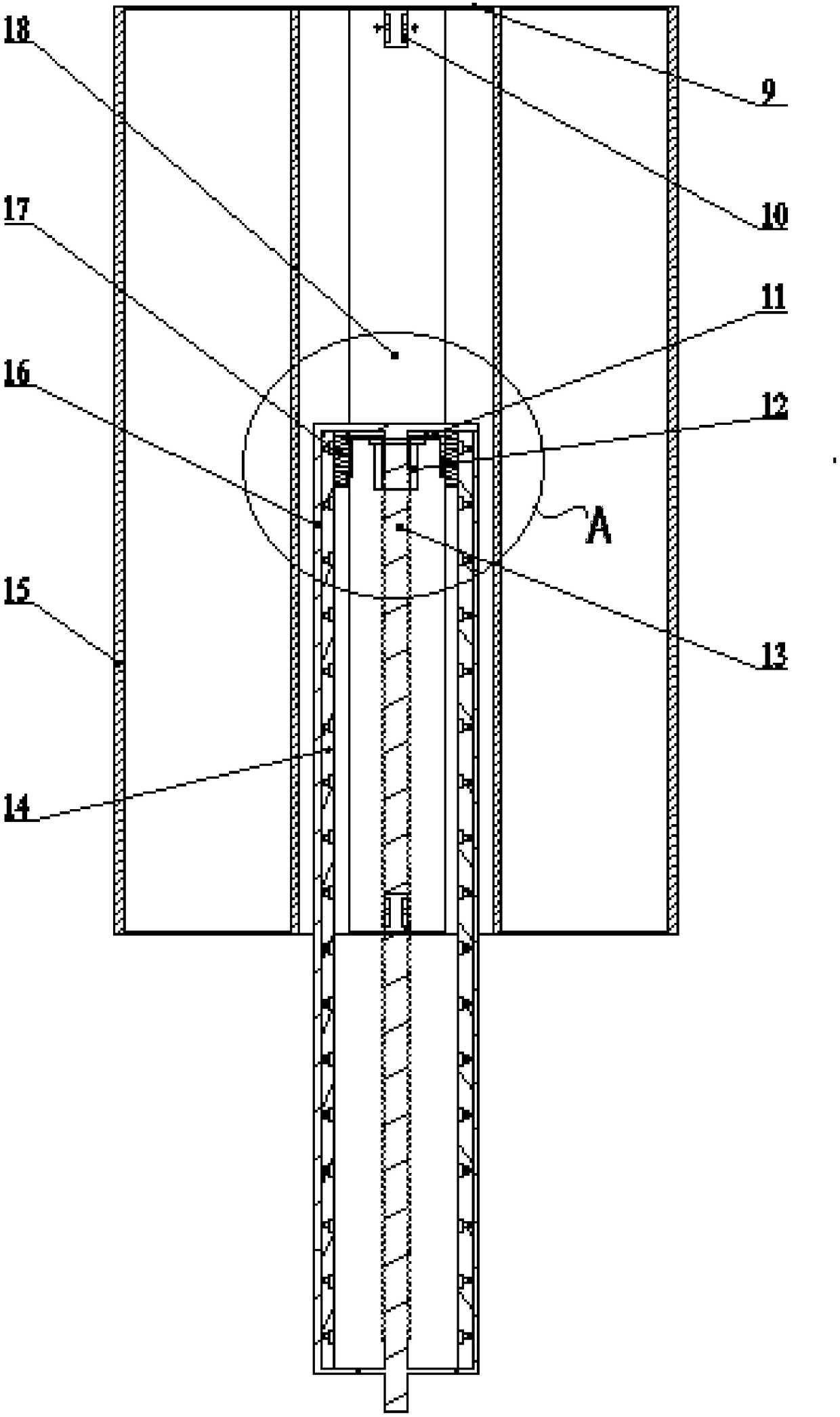
[0041] Such as figure 2 and Figure 5 As shown, the artificial porous barrier model positioning and installation device for wind tunnel test of the present invention corresponds to the position of the transparent test chamber 9 of the wind tunnel test system, wherein, the artificial porous barrier formed by the support stand 10 and the support base plate 18 Driven by the linkage mechanism below it, the clamping mechanism of the porous barrier model moves forward and backward in the horizontal direction, so that the artificial porous barrier model can freely advance to the designated position of the transparent test chamber 9, or withdraw from the transparent test chamber 9, and the control process is flexible And the movement is stable and r...


PUM


Abstract

The invention discloses an artificial porous barrier model positioning and installation device for wind tunnel test. In the positioning and installation device, an output shaft of a servo motor is coaxially connected a sliding lead screw, and a lead screw nut and the sliding lead screw are connected in a matched manner to form a lead screw pair; linear guide rails are arranged at the two sides ofthe sliding lead screw in parallel; sliding blocks are slidably connected on the linear guide rails; the sliding blocks at the two sides are fixedly connected with the lead screw nut in the middle through a sliding block connection member; a support plate is arranged above the lead screw nut, and the two sides of the support plate are fixedly connected with the sliding blocks; support frames are vertically arranged at the front and back ends of the support plate, and are used for fixedly connected with an artificial porous barrier model; under the drive of the sliding lead screw pair, the support frames, supported and driven by the support plate, slide back and forth along the linear guide rails; and furthermore, the artificial porous barrier model is driven to slide back and forth to realize positioning and installation. The device realizes automatic adjustment of the artificial porous barrier model in a wind tunnel test system, and improves adjusting precision of the artificial porous barrier model.

Description

technical field [0001] The invention belongs to the technical field of porous barrier model test devices and is suitable for wind tunnel tests, in particular to an artificial porous barrier model positioning and installation device for wind tunnel tests. Background technique [0002] The research on the dust retention effect of porous barriers mainly includes three research methods based on field measurement, wind tunnel test and numerical simulation. Comparability, inconsistency of test methods, and test models susceptible to interference from environmental conditions and other factors lead to differences in the amount of dust retained by the same porous barrier, making it impossible to obtain accurate test data. [0003] Compared with the method of field measurement, the real test environment can be simulated in the wind tunnel test, and controllable natural conditions including the amount of natural dust retention can be provided, including the dust source, environmental ...

Claims


Application Information

Patent Timeline
IPC IPC(8): G01M9/08G01M9/04
CPCG01M9/04G01M9/08
Inventor 郭丽马淑丽赵冬森王春委凯琪马云海陈东辉佟金
Owner JILIN UNIV
Learn More