
Temperature control system and method of combustion equipment

A temperature control system, temperature control method technology, applied in the control of combustion, lighting and heating equipment, dryers, etc., to solve problems such as unstable flame, extinguishment or loss, and inability to ensure safe and continuous operation of the burner

Inactive Publication Date: 2018-06-15
江苏旭润机电科技有限公司
View PDF6 Cites 4 Cited by
  • Summary
  • Abstract
  • Description
  • Claims
  • Application Information

AI Technical Summary

Problems solved by technology

Modulation of the fuel-air mixture may produce flame instability which may result in extinguishment or loss of flame condition in the burner, thereby interrupting the continuity of the combustion process and preventing safe an

Method used


Image

  • Temperature control system and method of combustion equipment
  • Temperature control system and method of combustion equipment
  • Temperature control system and method of combustion equipment

Examples


Embodiment 1

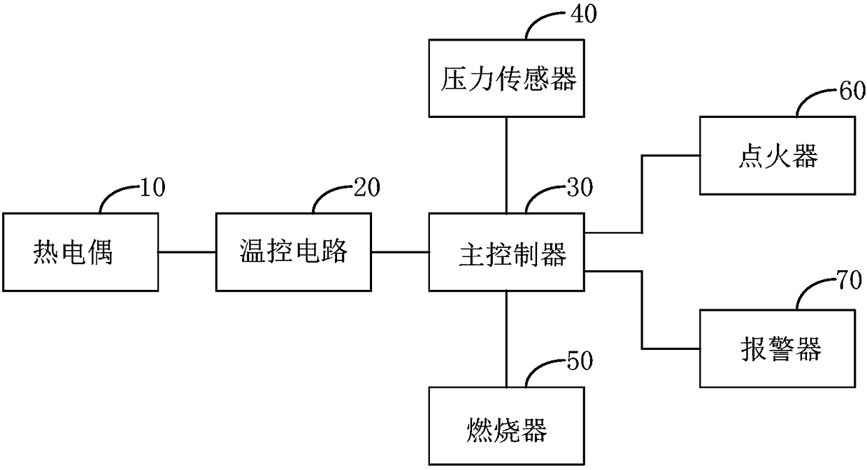
[0042] figure 1 It is a schematic diagram of the temperature control system of the combustion equipment provided by Embodiment 1 of the present invention.

[0043] refer to figure 1 , the system includes: thermocouple, temperature control circuit, main controller, pressure sensor and burner. respectively connected with the main controller;

[0044] Thermocouple, used to detect the current temperature in the drying room, and send the current temperature to the temperature control circuit;

[0045] The temperature control circuit is used to receive the current temperature sent by the thermocouple and send the current temperature to the main controller;

[0046] The pressure sensor is used to detect the current pressure signal of the burner and send the pressure signal of the burner to the main controller;

[0047]The main controller is used to receive the current pressure signal sent by the pressure sensor and the current temperature sent by the temperature control circuit, ...

Embodiment 2

[0062] image 3 The flow chart of the temperature control method of the combustion equipment provided by the second embodiment of the present invention.

[0063] refer to image 3 , the method includes the following steps:

[0064] Step S101, detecting the current temperature in the drying room.

[0065] Step S102, detecting the current pressure signal of the burner.

[0066] Step S103, comparing the current pressure signal with the preset pressure signal to obtain a flame signal.

[0067] Step S104, judge the flame state according to the flame signal, if the flame state is that the flame exists, then execute step S105; if the flame state is that the flame does not exist, execute step S106;

[0068] Step S105, compare the current temperature with the preset temperature, and control the heating of the burner according to the comparison result.

[0069] Step S106, receiving the ignition command information sent by the main controller, and providing an ignition source for th...


PUM


Abstract

The invention provides a temperature control system and method of combustion equipment. The temperature control system of the combustion equipment comprises a thermocouple, a temperature control circuit, a master controller, a pressure sensor and a combustor. The thermocouple detects the current temperature in a drying room. The temperature control circuit receives the current temperature sent bythe thermocouple and sends the current temperature to the master controller. The pressure sensor detects a current pressure signal of the combustor. The master controller receives the current pressuresignal sent by the pressure sensor and the current temperature sent by the temperature control circuit, the current pressure signal is compared with a preset pressure signal so that a flame signal can be obtained, the flame state is judged according to the flame signal, if the flame state indicates that a flame exists, the current temperature is compared with the preset temperature, and heating of the combustor is controlled according to the comparison result. The state of the flame in the combustor can be reflected through the pressure signal, the continuity of the combustion process is guaranteed, the combustor is accurately controlled, and the effect of finished products of textile fabrics is improved.

Description

technical field [0001] The invention relates to the technical field of combustion equipment, in particular to a temperature control system and method for combustion equipment. Background technique [0002] Commonly used textile equipment in the textile industry includes setting machines, steaming machines, printing machines and dryers, etc. These textile equipment work through burner heating. [0003] Specifically, during initial ignition of the burner, shortly after fuel is introduced into the burner, a stable flame is created and maintained in the burner to initiate and maintain combustion in the burner. During steady-state and transitional operations, the fuel-air mixture is continuously adjusted to optimize thermodynamic efficiency and reduce undesired emissions of nitrogen oxides, carbon monoxide, and other combustion by-product gases. Adjustments to the fuel-air mixture can create flame instabilities that can lead to extinguishment or loss of flame conditions in the c...

Claims


Application Information

Patent Timeline
IPC IPC(8): F23N5/10F26B21/10
CPCF23N5/10F23N2225/08F26B21/10
Inventor 徐国胤
Owner 江苏旭润机电科技有限公司
Learn More