
Concrete compressing device

A compaction device and concrete technology, applied in roads, road repairs, roads, etc., can solve the problems of easy loosening of concrete, poor flattening effect, and affecting paving quality, etc., and achieve high pavement strength and high paving quality.

Inactive Publication Date: 2018-06-15
马鞍山市鑫叶节能科技有限公司
View PDF5 Cites 5 Cited by
  • Summary
  • Abstract
  • Description
  • Claims
  • Application Information

AI Technical Summary

Problems solved by technology

The existing concrete paver has poor paving and compacting effect, and the paved concrete is easy to loosen, which affects the paving quality

Method used


Image

  • Concrete compressing device
  • Concrete compressing device
  • Concrete compressing device

Examples


Embodiment 1

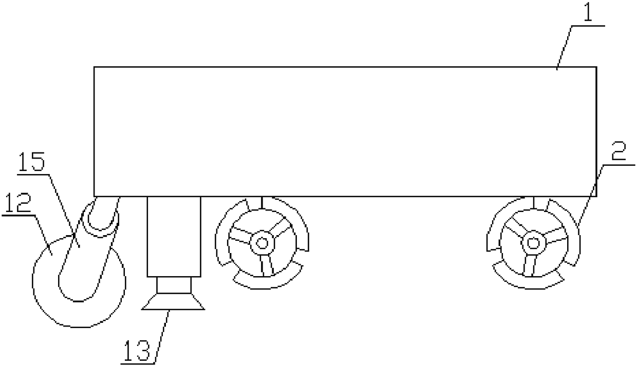
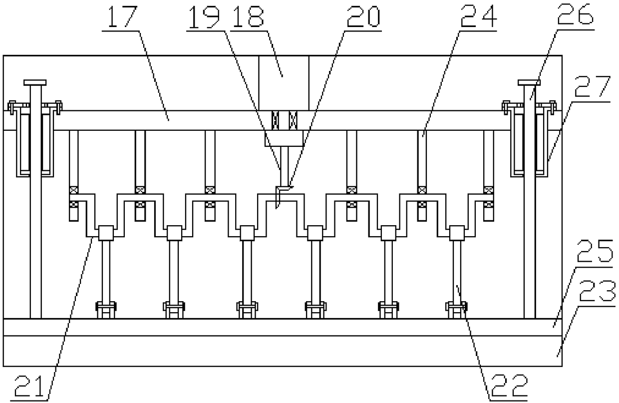
[0018] Embodiment 1: refer to Figure 1-2 , a concrete compacting device, comprising a storage vehicle 1, a tire 2 is provided at the bottom of the storage vehicle 1, a roller 12 is provided at the rear side of the bottom of the storage vehicle 1, and a roller 12 is arranged inside the roller 12. There is a rotating shaft, the two ends of the rotating shaft are provided with connecting long rods 15, and the top of the connecting long rod 15 is movable with a long rod. High road surface, the side of the rolling roller 12 is provided with a leveling device 13, the leveling device 13 includes a box, the inside of the box is provided with a support rod 17, and the top of the support rod 17 is provided with a motor 18, so The bottom of the motor 18 is provided with a rotating shaft 19, the bottom of the rotating shaft 19 is provided with a bevel gear assembly 20, the bottom of the bevel gear assembly 20 is provided with a crankshaft 21, the bottom of the crankshaft 21 is provided w...

Embodiment 2

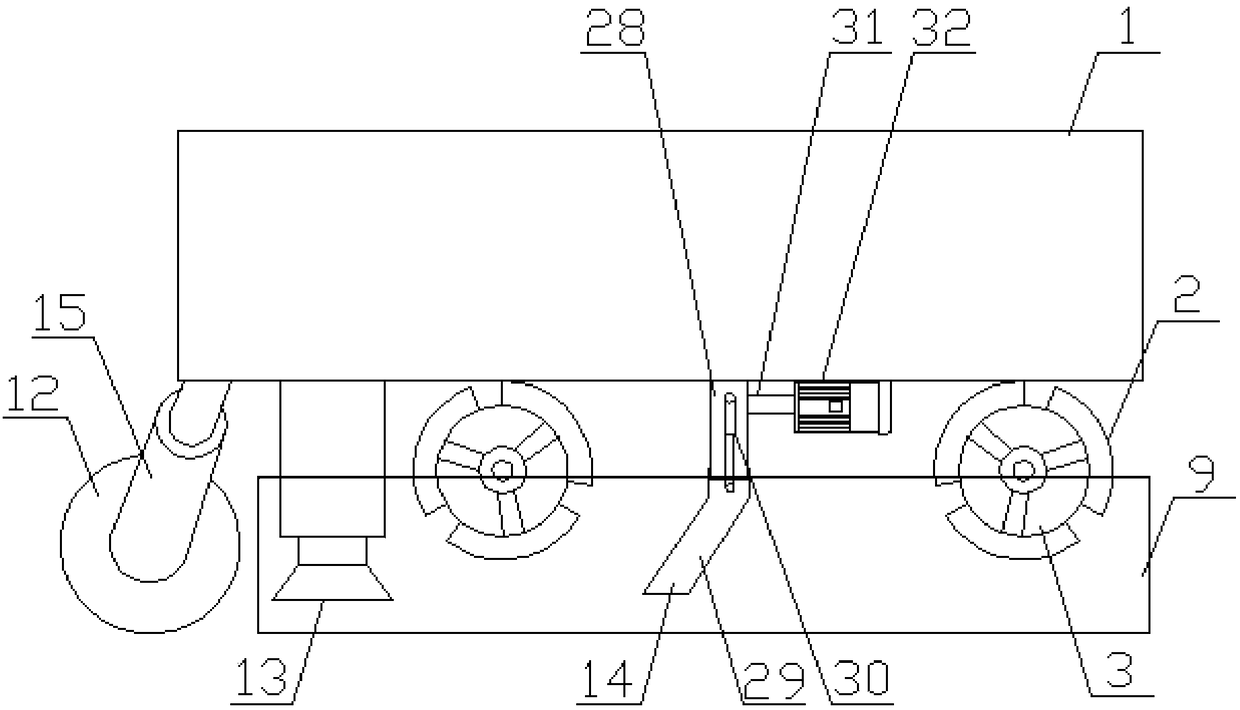
[0019] Embodiment 2: refer to Figure 2-5 , applying the present invention to a concrete paving device, comprising a storage vehicle 1, a tire 2 is provided at the bottom of the storage vehicle 1, and baffles 3 are provided on both sides of the tire 2, and the baffle 3 is set as Three and distributed in the outer side of the tire 2 in a circular array, the edge of the baffle 3 is provided with rounded corners, which is beneficial to the baffle 3 to squeeze the rail mold 9 inward during the rotation process, and arrange the rail mold 9 into a straight line to avoid The error caused by the manual laying of the rail formwork 9 leads to the deformation of the concrete laying and the later loosening and collapse. The inner side of the baffle plate 3 is provided with a push rod 4, and one end of the push rod 4 is provided with a pneumatic cylinder 5, and the inside of the pneumatic cylinder 5 is provided with a Piston 6, described pneumatic cylinder 5 one end is provided with air in...


PUM


Abstract

The invention discloses a concrete compressing device which comprises a storage trolley. Tires are arranged at the bottom of the storage trolley; a road pressing roller is arranged on the rear side ofthe bottom of the storage trolley; a levelling device is arranged on one side of the road pressing roller; a falling device is arranged on one side of the levelling device; a rotating shaft is arranged inside the road pressing roller; connecting long rods are arranged at the two ends of the rotating shaft, and long rods are movably arranged on the tops of the connecting long rods; and the long rods are fixedly connected with the storage trolley. According to the concrete compressing device, a motor drives a rotary shaft to rotate, a bevel gear assembly changes the rotating direction, and thusa crankshaft rotates to drive connecting rods and a pressing plate to make up-down reciprocating movement, so that paved concrete is compacted and tightened through a pressing foot, then the road surface is pressed to be leveled through the road pressing roller, therefore, the paving quality is high, and the road surface strength is high.

Description

technical field [0001] The invention relates to the field of paving devices, in particular to a concrete pressing device. Background technique [0002] The concrete paver is a construction machine that paves the mixed cement concrete along the given thickness, width and road type requirements of the subgrade, and then performs operations such as vibrating, leveling and troweling to complete the paving of the concrete pavement. Among them, the concrete paver is generally composed of a distributor, a pre-leveling mechanism, a vibrator (including a vibrating rod and a vibrating beam), a leveling machine, a trowel and other devices. Running on the rail formwork, it can be paved into a driving belt. The rail formwork is not only the driving track of the paver, but also the side formwork for paving the road. The specific construction process is as follows: first, the cement concrete that has been dumped on the roadbed is evenly spread on the roadbed according to a certain thickne...

Claims


Application Information

Patent Timeline
Patent Type & Authority Applications(China)
IPC IPC(8): E01C19/48
Inventor 叶伟
Owner 马鞍山市鑫叶节能科技有限公司
Learn More