X-ray source device

A technology of X-ray and source devices, applied in X-ray equipment, electrical components, etc., can solve problems such as complex design, weak signal, and difficult processing of vacuum tubes

Inactive Publication Date: 2018-06-12
NAT INST OF METROLOGY CHINA
View PDF9 Cites 0 Cited by
  • Summary
  • Abstract
  • Description
  • Claims
  • Application Information

AI Technical Summary

Problems solved by technology

One of the design schemes is to install a section of vacuum tube at the exit port of the X-ray machine, and place a detector at the other end of the vacuum tube. However, this scheme is complex in design and difficult to process the vacuum tube. At the same time, the vacuum degree in the vacuum tube is not well controlled. It is easy to grasp, which makes it difficult for the detector to collect

Method used


Image

  • X-ray source device
  • X-ray source device
  • X-ray source device

Examples


Embodiment 1

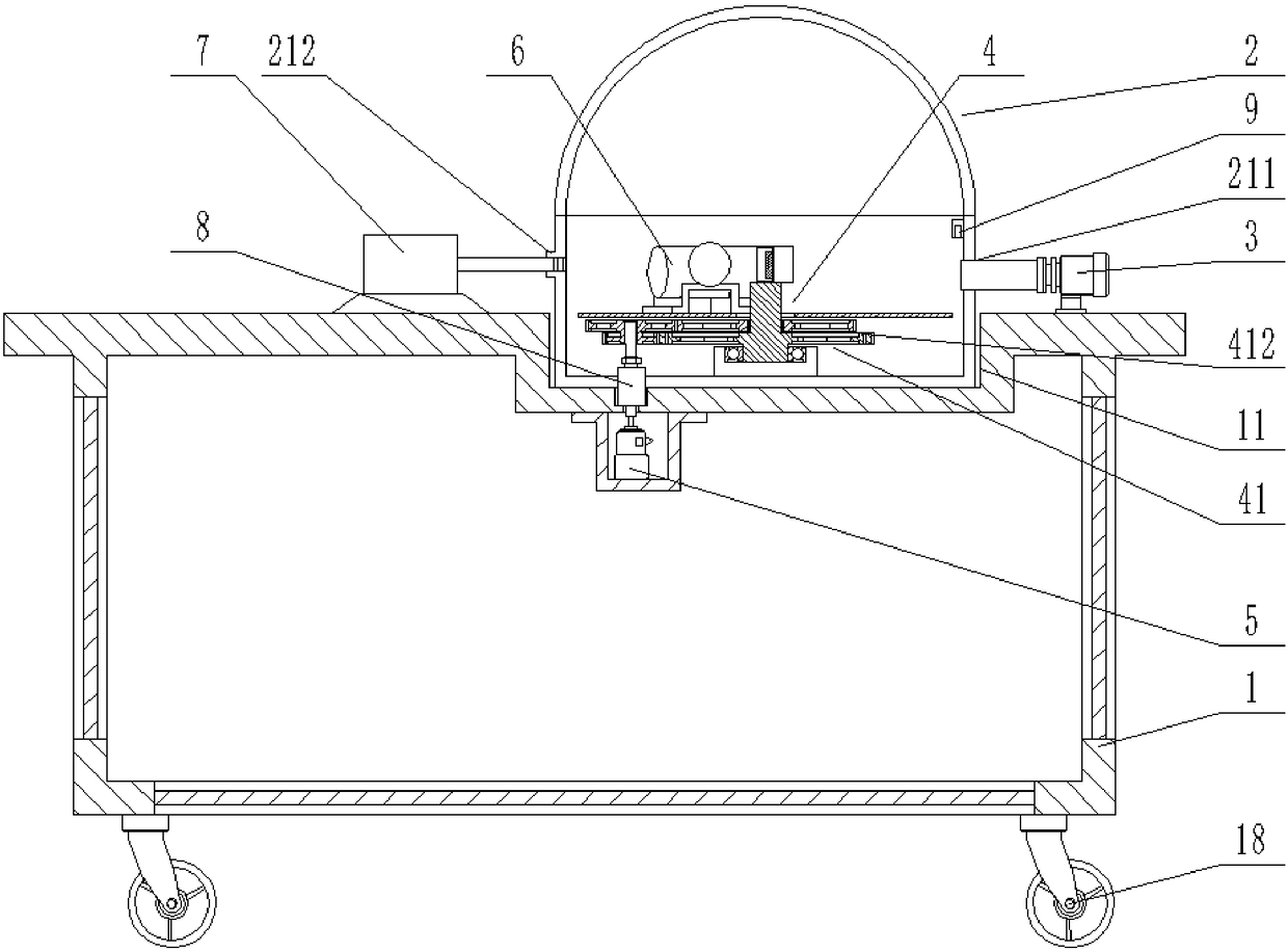
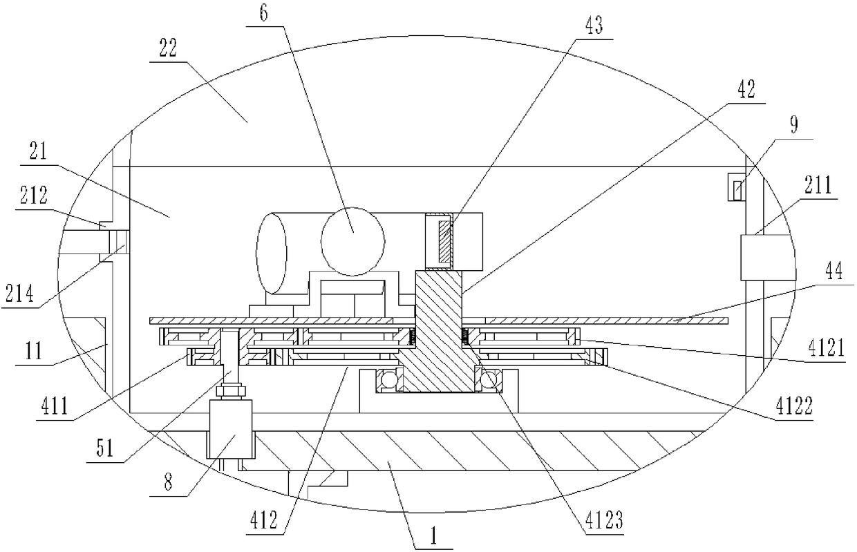
[0040] figure 1 , figure 2 They are respectively a structural schematic diagram and a partially enlarged view of the X-ray source device provided in Embodiment 1 of the present invention. combine figure 1 and figure 2 Shown:

[0041] The X-ray source device provided in Embodiment 1 of the present invention specifically includes: an installation base 1, a vacuum chamber 2, a dry pump 3, a single crystal monochromator 4, a drive motor 5, an open X-ray machine 6, an X-ray detector 7, Magnetic fluid seal 8, vacuum degree detector 9 and universal wheel 18.

[0042] Specifically, a fixing groove 11 is formed on the upper surface of the installation base 1 , and the vacuum chamber 2 is installed in the fixing groove 11 . Wherein, the vacuum chamber 2 includes a column cavity 21 and a hemispherical cavity 22, the column cavity 21 and the hemispherical cavity 22 are hermetically connected, and the column cavity 21 is provided with a connection port 211 and a window 212 in the ci...

Embodiment 2

[0059] Figure 5 , Figure 6 , Figure 7 and Figure 10 Respectively, the working state structural diagram and partial enlargement of the X-ray source device provided by Embodiment 2 of the present invention Figure 1 , partial enlargement Figure II And the schematic diagram of the top view of the non-working state. combine Figure 5 , Figure 6 , Figure 7 and Figure 10 Shown:

[0060] The X-ray source device provided in Embodiment 2 of the present invention specifically includes: a mounting base 1, a vacuum chamber 2, a plurality of outlet windows 212, a dry pump 3, a single crystal monochromator 4, a drive motor 5, an open X-ray machine 6, X-ray detector 7, arc track 12, driving trolley 13, placement plate 14, fixed frame 15, fixed ring 17, magnetic fluid seal 8, vacuum degree detector 9 and universal wheel 18.

[0061] Specifically, a fixing groove 11 is formed on the upper surface of the installation base 1 , and the vacuum chamber 2 is installed in the fixing...


PUM


Abstract

The embodiment of the invention relates to an X-ray source device. The device comprises an installation base. A fixing groove is formed in the upper surface of the installation base. A vacuum chamberis arranged in the fixing groove. The vacuum chamber comprises a cylindrical cavity and a hemispherical cavity which are hermetically connected with each other. A connecting port and one or more outlet windows are formed in the circumferential direction of the cylindrical cavity. A dry pump is arranged on the upper surface of the installation base. The dry pump is connected with the connecting port of the vacuum chamber. A single-crystal monochromator is arranged in the vacuum chamber. The single-crystal monochromator comprises a double-gear linkage device, a supporting column, a single crystal and a rotary table. A driving motor is arranged in the installation base. An open type X-ray machine is arranged on the rotary table. An X-ray detector is arranged on the installation base. According to the invention, the open type X-ray machine is selected, so that the overall vacuum degree can be controlled. The situation that low-energy X rays are filtered by the beryllium window of the X-raymachine is avoided. The problem that signals cannot be collected by the detector or collected signals are weak can be solved.

Description

technical field [0001] The invention relates to an X-ray source device, in particular to an X-ray source device for studying single-energy X-rays. Background technique [0002] At present, in the field of single-energy X-ray research, most of them focus on energy above 10keV, but the particle energy change in the low-energy range has a significant impact on the X-ray detector, so it is of great significance to accurately calibrate the detector in the low-energy range. However, the single-energy X-rays with energy below 10keV are easily absorbed by the air in the air, resulting in no signal received by the detector. [0003] In order to solve the problem that single-energy X-rays with energy below 10keV are easily absorbed by air, two design schemes are often used in the prior art. One of the design schemes is to install a section of vacuum tube at the exit port of the X-ray machine, and place a detector at the other end of the vacuum tube. However, this scheme is complex in...

Claims


Application Information

Patent Timeline
IPC IPC(8): H05G1/02
CPCH05G1/02
Inventor 郭思明吴金杰李梦石
Owner NAT INST OF METROLOGY CHINA
Why Eureka
Try Eureka