
Cable connector

The technology of a connector and the first cable is applied in the direction of connection, a device for relieving the stress at the connection of wires, and a two-part connection device, which can solve problems such as affecting continuous signal transmission, unstable connection, and intermittent connection, etc. Convenience, simple structure, and the effect of improving continuous stability

Inactive Publication Date: 2018-06-12
天津市小猫线缆股份有限公司
View PDF4 Cites 1 Cited by
  • Summary
  • Abstract
  • Description
  • Claims
  • Application Information

AI Technical Summary

Problems solved by technology

With the advancement and development of science and technology, the research on automation equipment is also advancing rapidly. As the connection line of signals between electrical appliances, instruments and other devices, the main function of the cable is to transmit electrical signals; during the use of the cable, the end of the cable needs to be Connected with the equipment line, the existing connection method often causes the problem of intermittent connection and unstable connection, which affects the continuous transmission of signals

Method used


Image

  • Cable connector

Examples


Embodiment Construction

[0016] It should be noted that, in the case of no conflict, the embodiments of the present invention and the features in the embodiments can be combined with each other.

[0017] In describing the present invention, it should be understood that the terms "center", "longitudinal", "transverse", "upper", "lower", "front", "rear", "left", "right", " The orientations or positional relationships indicated by "vertical", "horizontal", "top", "bottom", "inner" and "outer" are based on the orientations or positional relationships shown in the drawings, and are only for the convenience of describing the present invention and Simplified descriptions, rather than indicating or implying that the device or element referred to must have a particular orientation, be constructed and operate in a particular orientation, and thus should not be construed as limiting the invention. In addition, the terms "first", "second", etc. are used for descriptive purposes only, and should not be understood ...


PUM


Abstract

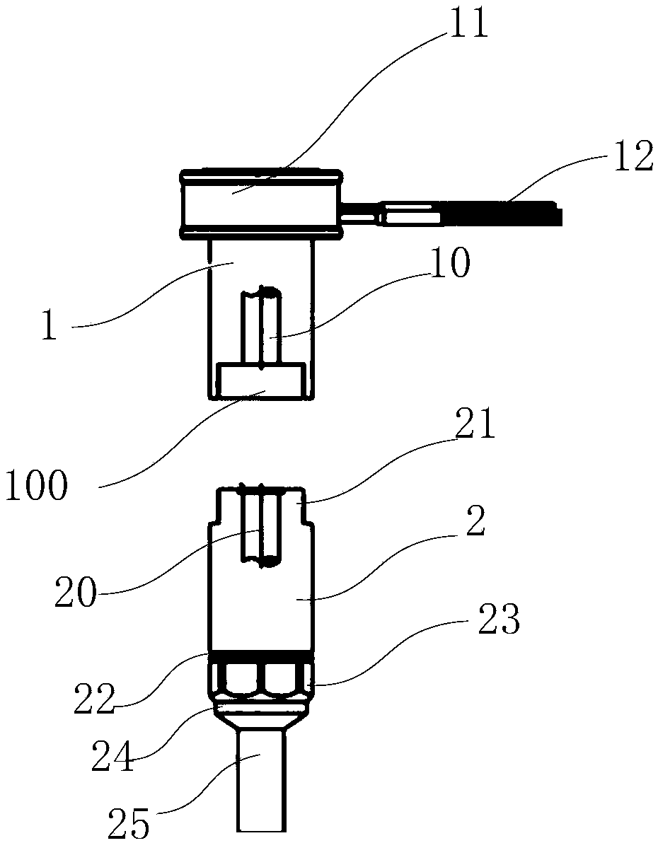
The invention provides a cable connector. The cable connector comprises a first joint and a second joint. The first joint is in butt joint with the second joint. A first cable is arranged in the firstjoint, and a first cable core of the first cable is arranged in a hollow structure in the first joint. A first joint cap is arranged at the end of the first joint, and the first cable penetrates thefirst joint cap. A second cable core is arranged in the second joint, and the second cable penetrates the end of the second joint. A locking nut and a cable pressing sleeve are arranged at the end ofthe second joint. The cable pressing sleeve sleeves the second cable, and is located in the second joint. The locking nut is locked at the end of the second joint in a threaded mode. The cable pressing sleeve is compressed at the second cable through the locking nut to lock the second cable at the second joint. The cable connector has the advantages of simple structure, convenience in use, and capability of improving connection stability at cable joints effectively and improving cable erection efficiency.

Description

technical field [0001] The invention belongs to the field of cables, in particular to a cable connector. Background technique [0002] The wire and cable industry is the second largest industry in China after the automobile industry, and the product variety satisfaction rate and domestic market share both exceed 90%. With the advancement and development of science and technology, the research on automation equipment is also advancing rapidly. As the connection line of signals between electrical appliances, instruments and other devices, the main function of the cable is to transmit electrical signals; during the use of the cable, the end of the cable needs to be To connect with the equipment line, the existing connection method often causes the problem of intermittent connection and unstable connection, which affects the continuous transmission of signals. Contents of the invention [0003] In view of this, the present invention aims to provide a cable connector to solve ...

Claims


Application Information

Patent Timeline
Patent Type & Authority Applications(China)
IPC IPC(8): H01R13/502H01R13/59H01R13/52H01R13/627H01R24/00
CPCH01R13/502H01R13/5202H01R13/59H01R13/627H01R24/00
Inventor 田卉莘
Owner 天津市小猫线缆股份有限公司
Learn More