Electro-permanent magnetic on-load voltage regulation switch

A technology of voltage regulating switch and electric permanent magnet, which is applied in the direction of electric switches, circuits, transformers, etc. It can solve the problems of inability to realize programmable logic control, large volume of voltage regulating switch device, and inability to control time quickly, so as to shorten the operation time , simple structure, and the effect of improving the reliability of the switch

Pending Publication Date: 2018-06-12
刁俊起
View PDF6 Cites 0 Cited by
  • Summary
  • Abstract
  • Description
  • Claims
  • Application Information

AI Technical Summary

Problems solved by technology

The on-load tap changer relies on the switch to switch the load current. The fast mechanism is the power source of the switch. At present, the fast mechanism mainly uses a spring energy release device, but the reliability of the spring is poor. Once the main spring is damaged, it will cause complete paralysis. The extension of time, the gradual deterioration of the spring elasticity or the breakage of the spring will cause serious consequences.
The patent document with the application number 201420849072.9 discloses a permanent magnet-driven on-load tap changer that uses a driving permanent magnet to control the contact or separation of the moving contact with the working contact and the transition contact. It is controlled by changing the position of the rotating permanent magnet. The action of the permanent magnet connected to the moving contact has the following problems: (1) The entire voltage regulating switch device is bulky and heavy; (2) Since the position change of the rotating permanent magnet takes time, it cannot be controlled quickly and flexibly; (3) Programmable logic control cannot be realized

Method used


Image

  • Electro-permanent magnetic on-load voltage regulation switch
  • Electro-permanent magnetic on-load voltage regulation switch
  • Electro-permanent magnetic on-load voltage regulation switch

Examples


Embodiment 1

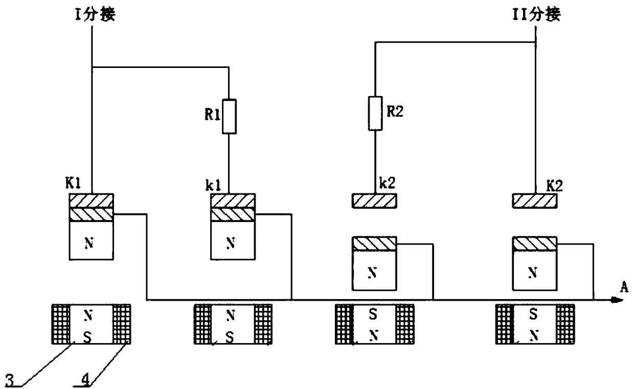
[0023] An electric permanent magnet on-load tap changer, including a switch circuit, the switch circuit includes an odd-number tap switch circuit and an even-number tap switch circuit with the same structure, and the tap switch circuit includes a working contact K1 , K2, transition contacts k1, k2 and transition resistances R1, R2 between the two, the working contacts K1, K2 and transition contacts k1, k2 are all facing a moving contact 1, and each moving contact 1 In parallel with each other, each moving contact 1 is fixed on one end of a permanent magnet 2, and the other end of each permanent magnet 2 is facing a moving contact driving mechanism; the moving contact driving mechanism includes a driving body 3 and is wound on The exciting coil 4 on the outer periphery of the driving body 3 applies a pulse current to the end of the exciting coil 4 . The driving body 3 is made of AlNiCo type magnetic steel with variable magnetic poles, and the permanent magnet 2 can be made of s...

Embodiment 2

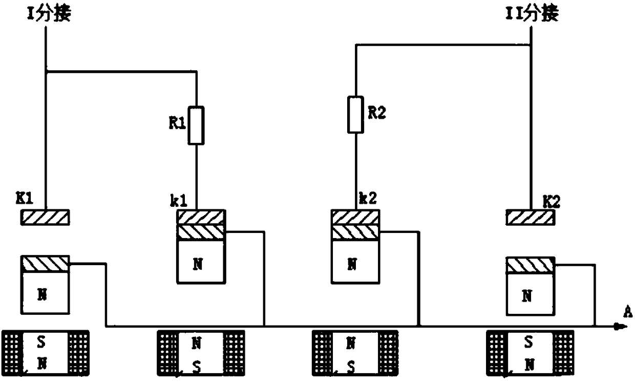
[0026] An electric permanent magnet on-load tap changer, including a switch circuit, the switch circuit includes an odd-number tap switch circuit and an even-number tap switch circuit with the same structure, and the tap switch circuit includes a working contact K1 , K2, transition contacts k1, k2 and transition resistances R1, R2 between the two; one end of the working contacts K1, K2 and transition contacts k1, k2 is connected to a permanent magnet 2, and the other ends are facing A moving contact 1, each moving contact 1 is connected in parallel with each other, and each moving contact 1 is connected to a driving mechanism; the driving mechanism includes a driving body 3 connected with the moving contact 1 and a driving body wound around the outer periphery of the driving body 3 Exciting coil 4, pulse current is applied to the end of exciting coil 4. The driving body 3 is made of AlNiCo type magnetic steel with variable magnetic poles, and the permanent magnet 2 can be made...


PUM


Abstract

The invention relates to an electro-permanent magnetic on-load voltage regulation switch. A tapping point switching circuit comprises a work contact, a transition contact and a transition resistor between the work contact and the transition contact; the work contact and the transition contact are both directly opposite to a moving contact, the moving contacts are connected with each other in parallel, each moving contact is fixed at one end of a permanent magnet, the other end of each permanent magnet is directly opposite to a moving contact driving mechanism; each moving contact driving mechanism comprises a driving body and a magnet exciting coil winding on the periphery of the driving body, and a pulse current is applied at the end portion of the magnet exciting coil. The electro-permanent magnetic on-load voltage regulation switch has the advantages that the structure is simple, the pulse current is applied at the end portion of the magnet exciting coil to control the opening and closing of each contact, the motion is reliable, the programmable logic control is achieved, the control is convenient and flexible, the service life of the switch is prolonged, and the accident occurrence rate is reduced.

Description

technical field [0001] The invention relates to an on-load voltage regulating switch, in particular to an electric permanent magnet on-load voltage regulating switch. Background technique [0002] The transformer changes the number of effective excitation coil turns on the high voltage side of the transformer by switching from one tap to another to achieve voltage regulation. The on-load tap changer relies on the switch to switch the load current. The fast mechanism is the power source of the switch. At present, the fast mechanism mainly uses a spring energy release device, but the reliability of the spring is poor. Once the main spring is damaged, it will cause complete paralysis. The prolongation of time, the gradual deterioration of the spring elasticity or the breakage of the spring will cause serious consequences. The patent document with the application number 201420849072.9 discloses a permanent magnet-driven on-load tap changer that uses a driving permanent magnet t...

Claims


Application Information

Patent Timeline
Patent Type & Authority Applications(China)
IPC IPC(8): H01H9/00H01F29/04
CPCH01F29/04H01H9/0016H01H9/0027
Inventor 刁俊起
Owner 刁俊起
Why Eureka
Try Eureka