Gate scan drive circuit
A driving circuit and gate scanning technology, applied in static indicators, instruments, etc., can solve problems such as increasing circuit complexity, reducing circuit reliability, and difficulty in opening the pull-up control node netAn normally, saving layout space and reducing effect of quantity
- Summary
- Abstract
- Description
- Claims
- Application Information
AI Technical Summary
Problems solved by technology
Method used
Image
Examples
Embodiment 1
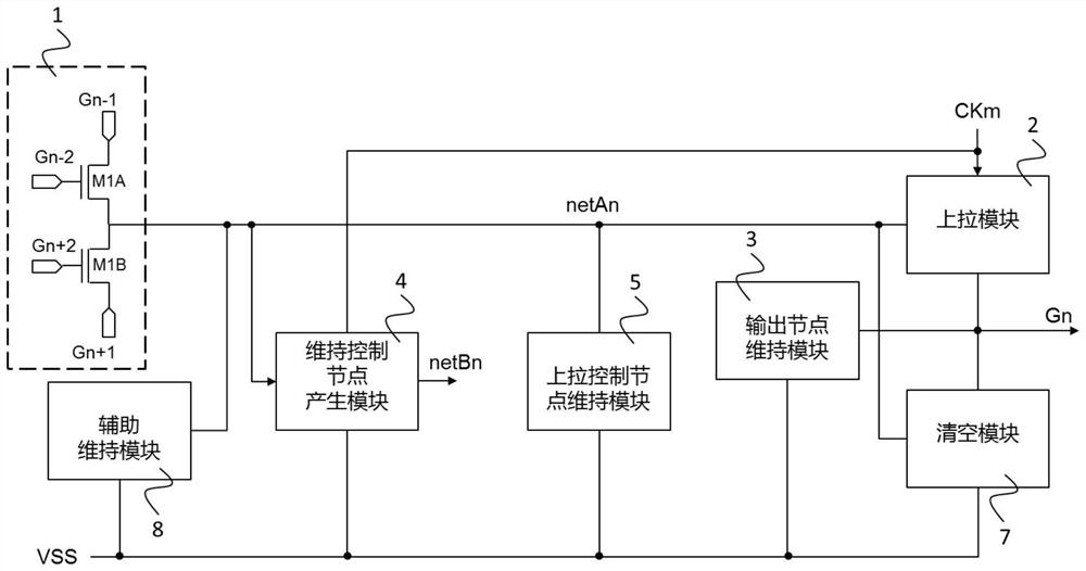
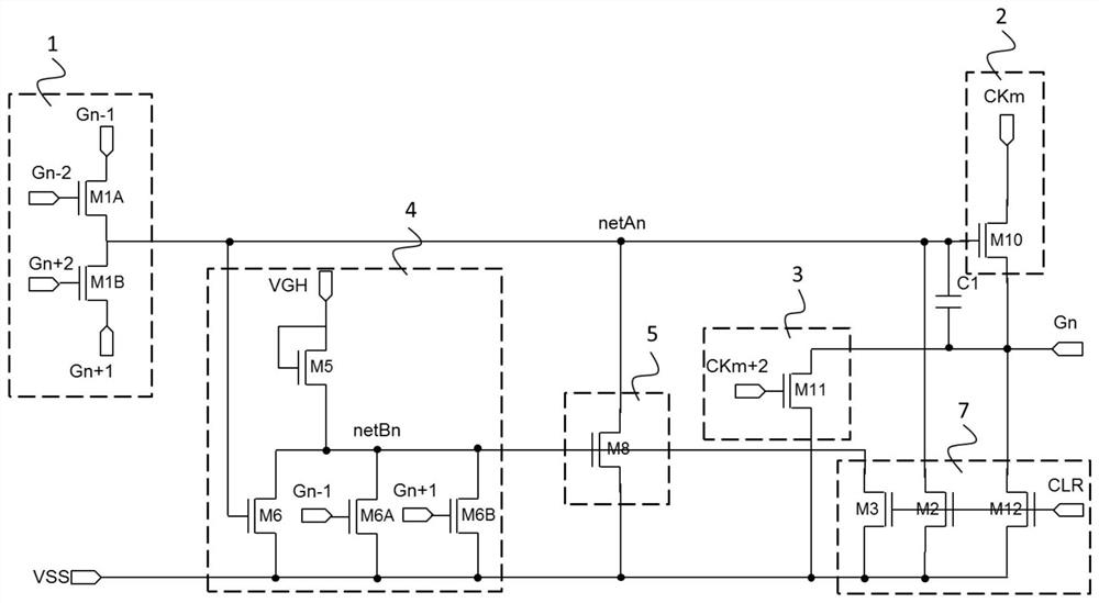
[0062] Such as image 3 Shown is a circuit diagram of Embodiment 1 of a gate scanning drive circuit, as image 3 As shown, the nth level drive circuit unit includes a pull-up control module 1 , a pull-up module 2 , an output node maintenance module 3 , a maintenance control node generation module 4 and a pull-up control node maintenance module 5 .
[0063] The pull-up control module 1, the pull-up module 2, the pull-up control node maintenance module 5, and the maintenance control node generation module 4 are connected to the pull-up control node netAn; the pull-up module 2, the output node maintenance module 3, and the maintenance control node generation module 4 and the pull-up control node maintenance module 5 both input low-level VSS; the pull-up module 2 and the output node maintenance module 3 are connected to the scanning signal line of the current stage.
[0064] Such as image 3 As shown, specifically, the pull-up control module 1 includes a first thin film transist...
Embodiment 2
[0099] Figure 6 It is a schematic circuit diagram of Embodiment 2 of a gate scanning driving circuit of the present invention. The second embodiment is improved on the basis of the first embodiment, and the specific improvements are as follows:
[0100] 1. The maintenance control node generation module 4 inputs the first low-frequency clock signal LC1 and the second low-frequency clock signal LC2, the first low-frequency clock signal LC1 and the second low-frequency clock signal LC2 are mutually inverse, and alternately take high level or low level .
[0101] 2. The maintenance control node generation module 4 includes a first maintenance control node generation module 41 and a second maintenance control node generation module 42 .
[0102] The first maintenance control node generation module 41 and the pull-up control node maintenance module 5 are connected to the first maintenance control node netCn; the second maintenance control node generation module 42 and the pull-up...
Embodiment 3
[0110] Figure 7 It is a schematic circuit diagram of Embodiment 3 of a gate scanning driving circuit of the present invention. The third embodiment is improved on the basis of the second embodiment, and the specific improvements are as follows:
[0111] 1. The output node maintaining module 3 includes a twenty-third thin film transistor M11A and a twenty-sixth thin film transistor M11B. The control end of the twenty-third thin film transistor M11A is connected to the first sustain control node netCn of the n-th stage driving circuit unit, and the two access ends of the twenty-third thin film transistor M11A are respectively connected to the low level VSS and the scanning signal line of the current stage. The control end of the twenty-fourth thin film transistor M11B is connected to the second sustain control node netDn of the n-th stage driving circuit unit, and the two access ends of the twenty-fourth thin film transistor M11B are respectively connected to the low level VSS...
PUM
 Abstract
Description
Claims
Application Information
 - R&D
- Intellectual Property
- Life Sciences
- Materials
- Tech Scout
- Unparalleled Data Quality
- Higher Quality Content
- 60% Fewer Hallucinations
Browse by: Latest US Patents, China's latest patents, Technical Efficacy Thesaurus, Application Domain, Technology Topic, Popular Technical Reports.
© 2025 PatSnap. All rights reserved.Legal|Privacy policy|Modern Slavery Act Transparency Statement|Sitemap|About US| Contact US: help@patsnap.com


