A light valve device
A device and light valve technology, applied in the field of light valve devices, can solve the problems of long manufacturing process time and affect the optical performance of the device, and achieve the effect of long service life
- Summary
- Abstract
- Description
- Claims
- Application Information
AI Technical Summary
Problems solved by technology
Method used
Image

Examples
Embodiment 1
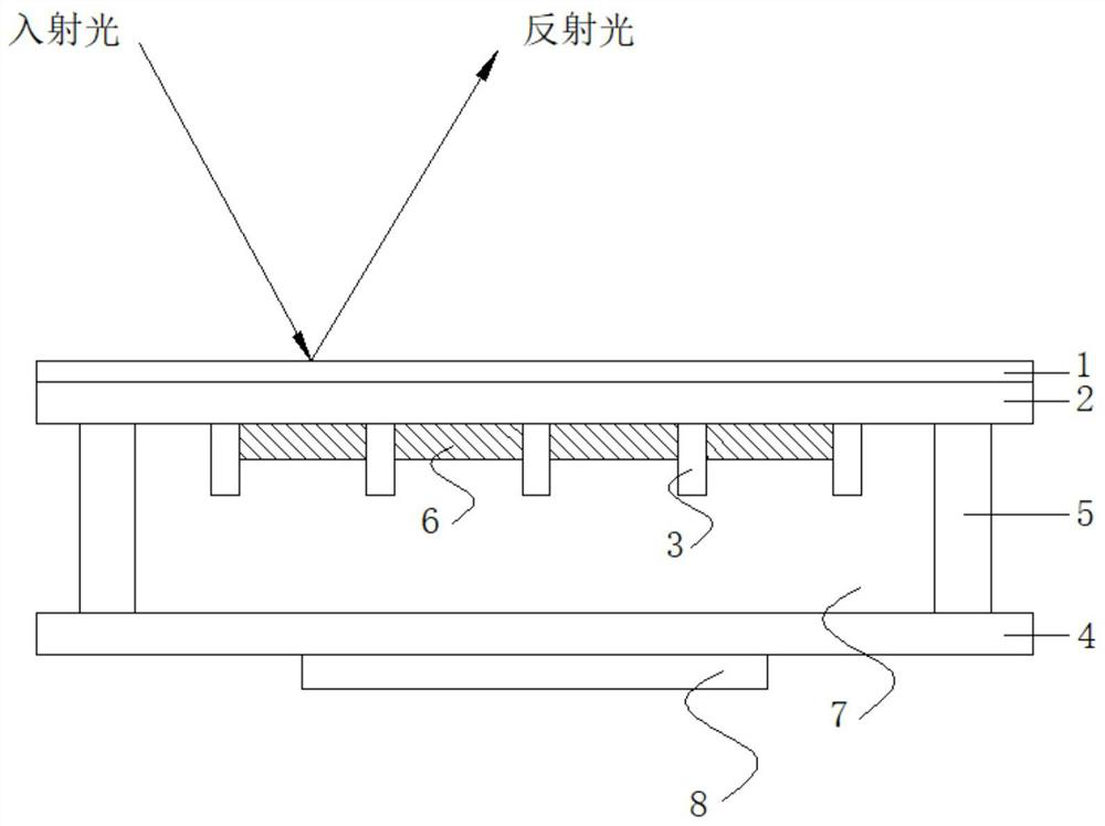
[0027] see figure 1 and figure 2 , the direction of incident light and reflected light in the figure represents the viewing direction of the eyes. This embodiment provides a light valve device, including a substrate one 1, a hydrophobic layer 2, a pixel wall 3, a substrate two 4 and a force device arranged in sequence. The force application device includes a pressing piece 8 and a piezoelectric control switch (not shown) linked on the pressing piece 8, and the pressing piece 8 is arranged on the opposite side of the substrate one 1 on the substrate two 4, and the piezoelectric control switch (not shown) The control switch includes a signal input terminal, and controls the degree of deformation of the pressing sheet according to the magnitude of the input voltage of the signal input terminal, so as to generate corresponding pressure on the second substrate 4, and a sealing frame 5 is formed between the first substrate 1 and the second substrate 4 The filling area is filled wi...
Embodiment 2
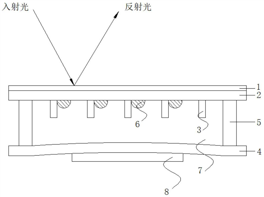
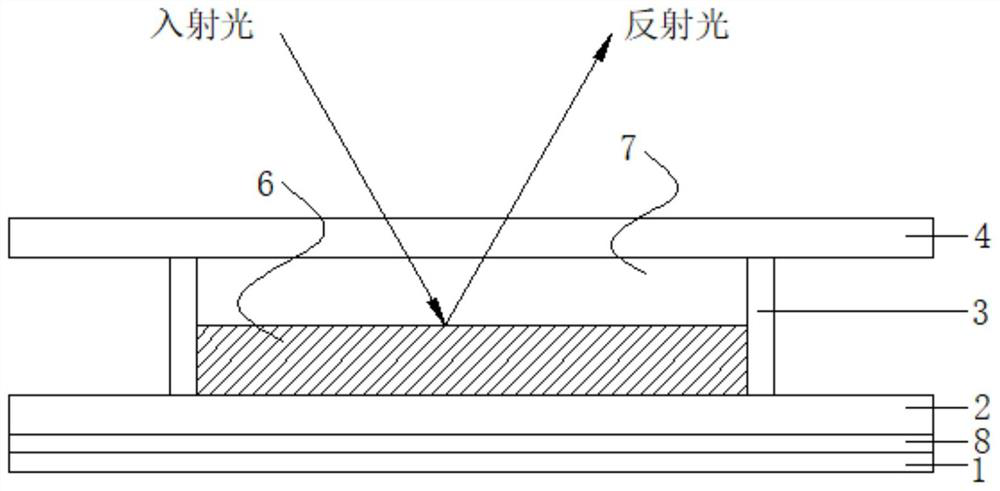
[0032] see image 3 and Figure 4 , the direction of incident light and reflected light in the figure represents the viewing direction of the eyes. This embodiment provides a light valve device, including a substrate one 1, a force application device 8, a hydrophobic layer 2, a pixel wall 3 and a substrate two 4 arranged in sequence, so that A filling area is formed between the first substrate 1 and the second substrate 4, and the filling area is filled with ink 6 and liquid two 7, the liquid two 7 and the ink 6 are incompatible with each other, and the force applying device 8 is a deformable film, which is deformed after the voltage is connected, and exerts pressure on the hydrophobic layer 2 in contact with it through its own deformation, thereby causing a certain pressure on the liquid in the filling area, and the liquid filled in the filling area is subjected to Squeeze, the liquid 2 7 with high viscosity squeezes the ink 6 to a corner, and light passes through the substr...
Embodiment 3
[0036] This embodiment provides a light valve device, which is the same as Embodiment 1, except that the liquid filled in the filling area is a polyether compound such as polydodecyl ether, polyethylene glycol ether, and the like.
PUM
| Property | Measurement | Unit |
|---|---|---|
| contact angle | aaaaa | aaaaa |
| contact angle | aaaaa | aaaaa |
| thickness | aaaaa | aaaaa |
Abstract
Description
Claims
Application Information
 - Generate Ideas
- Intellectual Property
- Life Sciences
- Materials
- Tech Scout
- Unparalleled Data Quality
- Higher Quality Content
- 60% Fewer Hallucinations
Browse by: Latest US Patents, China's latest patents, Technical Efficacy Thesaurus, Application Domain, Technology Topic, Popular Technical Reports.
© 2025 PatSnap. All rights reserved.Legal|Privacy policy|Modern Slavery Act Transparency Statement|Sitemap|About US| Contact US: help@patsnap.com