
Spring thermal relaxation testing device

A test device and thermal relaxation technology, applied in the field of measurement and control, can solve problems such as economic losses

Inactive Publication Date: 2018-06-12
凤城市凯驰内燃机配件有限公司
View PDF5 Cites 2 Cited by
  • Summary
  • Abstract
  • Description
  • Claims
  • Application Information

AI Technical Summary

Problems solved by technology

These phenomena are not uncommon in daily life, and severe cases will cause huge economic losses
[0007] The device for measuring spring relaxation generally adopts a relatively primitive experimental device, and there is no measurement and control device that can automatically detect springs at different temperatures and under different tension states.

Method used


Image

  • Spring thermal relaxation testing device
  • Spring thermal relaxation testing device
  • Spring thermal relaxation testing device

Examples


Embodiment Construction

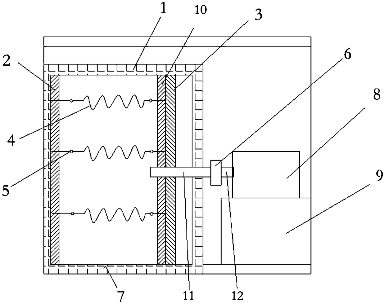
[0016] The present invention is specifically described below in conjunction with accompanying drawing, as figure 1 , figure 2 As shown, the present invention includes a high-temperature box 1, a fixed heating layer 2 and a movable heating layer 10 are arranged in the high-temperature box 1, the fixed heating layer 1 and the movable heating layer 10 are oppositely arranged, and the fixed heating layer 1 and the movable heating layer 10 The heating element is arranged inside; the hook 5 is set on the fixed heating layer 2 and the movable heating layer 10, and the spring 4 is hung between the two opposite hooks 5; fixed, the pull rod 11 is connected to one end of the pull gauge 6, the other end of the pull gauge 6 is fixed to the hydraulic pull rod 12, the hydraulic pull rod 12 is driven by the hydraulic tank 8, and the hydraulic tank is fixed on the box base 9; the movable heating layer 10 is set outside Insulation layer 3, the insulation layer 3 and the movable heating layer ...


PUM


Abstract

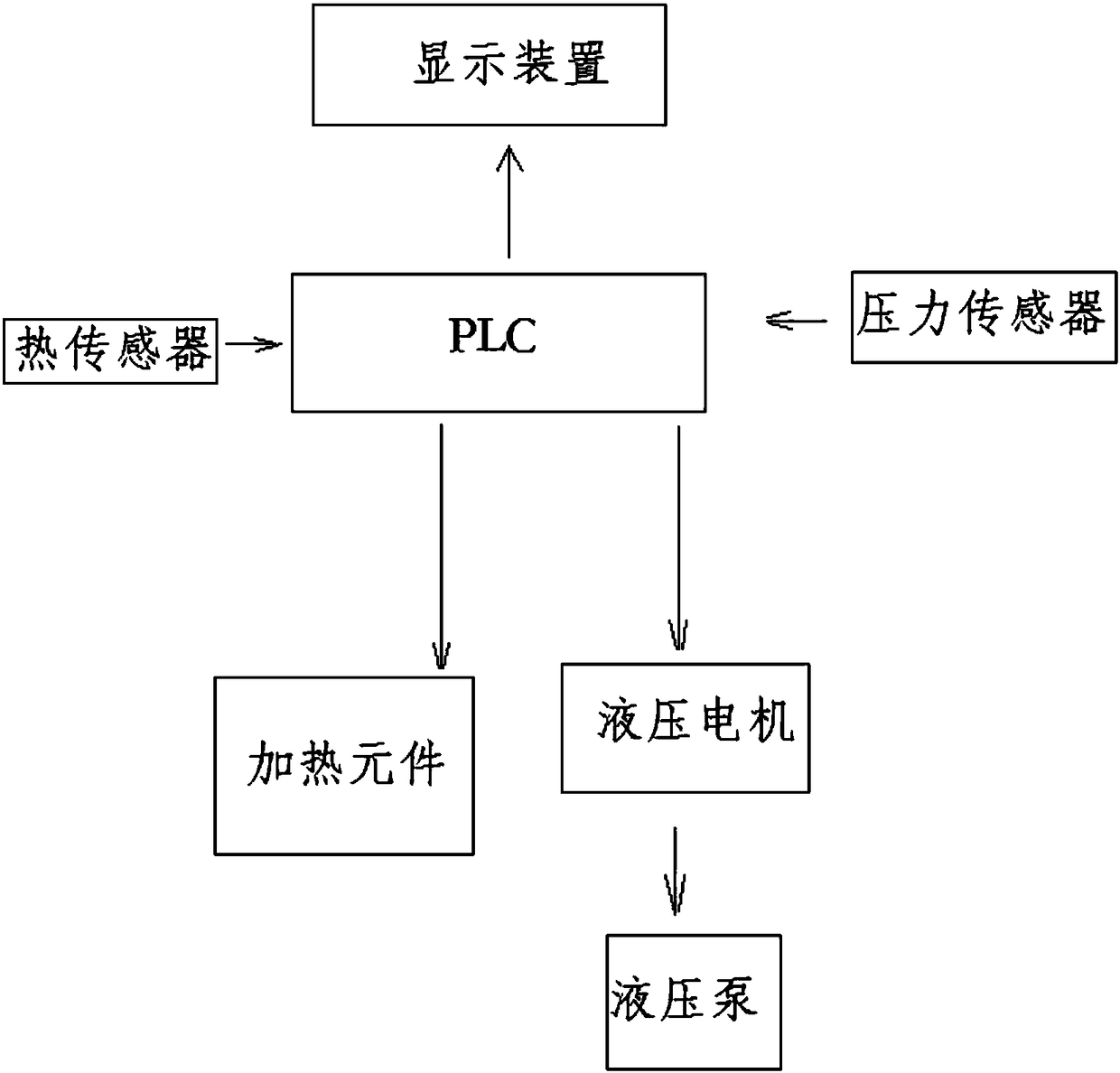
The invention discloses a spring thermal relaxation testing device, which comprises a high temperature box, wherein the high temperature box is internally provided with a fixed heating layer and a movable heating layer, the fixed heating layer and the movable heating layer are oppositely arranged, the fixed heating layer and the movable heating layer are internally provided with a heating element;the fixed heating layer and the movable heating layer are provided with hooks, and each spring is hung between two oppositely arranged hooks; the fixed heating layer is fixed with the inner wall of the high temperature box, the movable heating layer is fixed with a pull rod, the pull rod is connected with a tension meter, the tension meter is fixed with a hydraulic pull rod, and the hydraulic pull rod is driven by a hydraulic tank; the movable heating layer is externally provided with a heat preservation layer, and the heat preservation layer and the movable heating layer are fixed into a whole and arranged on a guide rail at the lower part of the high temperature box. The spring thermal relaxation testing device has the advantages that the heating temperature and received tension of thesprings can be controlled due to adoption of a temperature controller and a pressure control device which are controlled by a PLC, time control is performed according to a built-in time controller ofthe PLC, and thus relaxation parameters of the springs can be accurately measured and controlled.

Description

technical field [0001] The invention relates to the technical field of measurement and control, in particular to a spring relaxation measurement and control device. Background technique [0002] The relaxation rate ε of the spring is expressed as a percentage of load loss after the spring test: [0003] [0004] In the formula, F——the spring load measured before the test; [0005] Fi - the spring load determined after the test. [0006] The essence of stress relaxation is that the material produces microplastic deformation under the action of stress, and gradually accumulates it. Under the premise of keeping the strain or displacement constant, it is a phenomenon that the stress decreases with time. Stress relaxation is a fairly common phenomenon. It exists not only in elastic elements or components made of metal materials, but also in components made of non-metallic materials. It is a variety of mechanical springs (such as valve springs and buffer springs, etc.) One o...

Claims


Application Information

Patent Timeline
IPC IPC(8): G01M13/00
CPCG01M13/00
Inventor 袁清智张敬华张超伟杜军于辉
Owner 凤城市凯驰内燃机配件有限公司
Learn More