Eureka AIR delivers breakthrough ideas for toughest innovation challenges, trusted by R&D personnel around the world.

Self-inspection method and system for sensors of industrial furnaces and boilers

A sensor and industrial furnace technology, which is applied to the structural details of instruments, scientific instruments, gas analyzers, etc., can solve the problem of high cost of installation and layout equipment, and achieve the effect of convenient self-inspection and improved accuracy.

Active Publication Date: 2018-06-12
CHONGQING GIENT HEATING IND
View PDF12 Cites 4 Cited by
  • Summary
  • Abstract
  • Description
  • Claims
  • Application Information

AI Technical Summary

Problems solved by technology

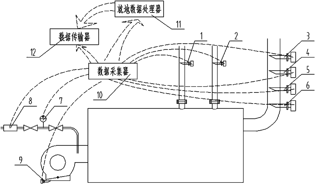
[0005] The purpose of the present invention is to provide a sensor self-inspection system and method for boilers, which does not need to add additional sensors, and can solve the problems of the existing sensor self-inspection on the installation and arrangement of the field environment and the high cost of equipment

Method used


Image

  • Self-inspection method and system for sensors of industrial furnaces and boilers
  • Self-inspection method and system for sensors of industrial furnaces and boilers
  • Self-inspection method and system for sensors of industrial furnaces and boilers

Examples


Embodiment Construction

[0019] The present invention will be further described below in conjunction with the accompanying drawings and embodiments.

[0020] The present invention is used for the sensor self-inspection method of industrial furnaces and boilers, which is different from the prior art in which the detection values ​​between sensors of the same type are used to verify each other, and is also different from the prior art in which paired sensors are set at the same detection point , but start from the whole sensor system to build a data relationship network. The data of different detection points are related to the operation status of the entire boiler and irrelevant, and there are data correlations and non-correlations between different detection points. The method of the present invention models the above-mentioned relationship network from the aspect of data relevance in a direction different from the conventional thinking, and mainly divides into the following four types of mathematical ...


PUM


Abstract

The invention relates to a self-inspection method for sensors for industrial furnaces and boilers. The method comprises the steps of modeling and self-inspection; according to modeling, from the wholesensor system, a relative network on data is constructed, data at different detecting points is related or unrelated to the whole boiler operation state, data relevance and non-relevance exist amongthe different detecting points, and four classes of mathematic models are built; according to self-inspection, a detection value actually detected by a sensor needing self-inspection is compared witha detection theoretical value inside at least one of the four classes of mathematic models in real time, and if the difference between the two values exceeds the tolerant range, it is determined thatthe sensor is drifted or damaged. The invention further relates to a self-inspection system for sensors for industrial furnaces and boilers. No multiple similar sensors need to be configured, and theproblem that an existing self-inspection method for comparing multiple similar sensors is high in equipment cost and is limited by field installation arrangement is solved.

Description

technical field [0001] The invention relates to industrial furnaces and boilers, in particular to a sensor self-inspection method and system for industrial furnaces and boilers. Background technique [0002] my country's industrial furnaces and industrial boilers are typical high-energy-consuming, high-emission, and high-pollution equipment. Equipment can be provided. With the intensification of industry competition and the country's increasingly stringent energy conservation and environmental protection requirements, in order to improve the operational energy efficiency of industrial kilns and industrial boilers, it has better controllability in terms of combustion efficiency, operational safety, energy conservation and environmental protection, etc. The rapid development of Internet of things technology and artificial intelligence technology in industrial furnace and boiler industry. As the basis for supporting the Internet of Things and artificial intelligence technology...

Claims


Application Information

Patent Timeline
Patent Type & Authority Applications(China)
IPC IPC(8): G01F25/00G01L27/00G01K15/00G01N33/00
CPCG01K15/007G01L27/00G01N33/0031G01N33/0037G01N33/004G01F25/10
Inventor 赵征鹏彭俊杨钢彭海洋官文鸿陈洋刘琪王文恬丁朝阳
Owner CHONGQING GIENT HEATING IND
Why Eureka
Eureka Blog
Learn More