
Spray electronic candle

A technology for electronic candles and candles, which is applied to electric light sources, circuit layout, heating methods, etc., can solve the problems of shorter candles, hidden safety hazards, and low ornamental quality, and achieves guaranteed atomization effect, quick replacement, and simple and convenient water injection operation. Effect

Inactive Publication Date: 2018-06-12
NANTONG YA TAI CANDLE ARTS & CRAFTS
View PDF6 Cites 5 Cited by
  • Summary
  • Abstract
  • Description
  • Claims
  • Application Information

AI Technical Summary

Problems solved by technology

[0002] Candles are a kind of decorative daily necessities. Traditional candles are mainly used for lighting and are realized by burning wax oil. However, burning makes candles gradually become shorter and exhausted. At the same time, with the development of society, the functions of candles are no longer available. Limited to lighting, it also plays the role of decoration and increasing the atmosphere. At birthday parties, friends' dinners, and lovers' dates, light a few candles. The flickering candles can add a romantic atmosphere. However, burning candles are not only troublesome to operate, Moreover, there is a great potential safety hazard. Electronic candles have appeared in response to this phenomenon, but ordinary electronic candles can only emit light, and at most can emit music.

Method used


Image

  • Spray electronic candle
  • Spray electronic candle
  • Spray electronic candle

Examples


Embodiment Construction

[0027] The present invention will be further described below in conjunction with accompanying drawing:

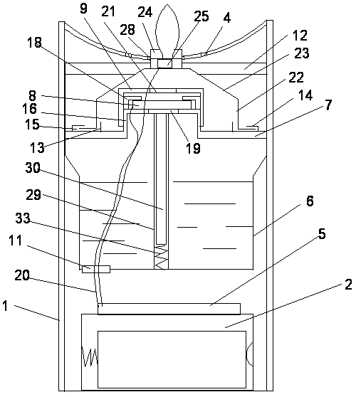
[0028] Such as Figure 1~5 As shown, a spray electronic candle disclosed by the present invention includes a candle body 1 with a cavity, a spray mechanism is installed in the cavity, a battery box 2 is installed at the bottom, and a flame head installation hole 3 is provided on the upper surface of the candle body , and the upper surface of the candle body is also provided with a plurality of water injection holes 4, the water injection holes 4 are distributed on the outside of the flame head installation hole, the upper surface of the battery box is equipped with a circuit board 5, and the bottom surface is embedded with a toggle switch.

[0029] The spraying mechanism includes a water storage box 6, a fixed base 7, an atomizing sheet 8, a silicone waterproof cover 9, a water inlet cover 10 and a water absorption mechanism, specifically:

[0030] The water storage box 6 ...


PUM


Abstract

The invention discloses a spray electronic candle. The spray electronic candle comprises a candle body with a cavity, a spraying mechanism is installed in the cavity, and a battery box is installed atthe bottom part of the cavity; the upper surface of the candle body is provided with a flame head mounting hole, and multiple water injection holes are formed in the upper surface of the candle body;a circuit board is installed on the upper surface of the battery box, and a toggle switch is embedded in the bottom surface of the battery box; the spraying mechanism comprises a water storage box, afixing base is arranged in the water storage box, an atomizing sheet is arranged on the fixing base, the exterior of the water storage box is covered by a water inlet cover, and a water absorption mechanism is installed at the bottom part of the fixing base; and water in the water storage box is guided to the atomizing sheet to be atomized through a water diversion core, and generated spray is sprayed out from the upper part. The spray electronic candle spray electronic candle can be assembled inside the electronic candle shell, when a flame head is lightened, the spray is sprayed out so thatthe air can be humidified, and the sprayed spray is matched with the flame head, and therefore the atmosphere of flaming burning and flue gas filling is realized.

Description

technical field [0001] The invention relates to an electronic candle, in particular to a spray electronic candle. Background technique [0002] Candles are a kind of decorative daily necessities. Traditional candles are mainly used for lighting and are realized by burning wax oil. However, burning makes candles gradually become shorter and exhausted. At the same time, with the development of society, the functions of candles are no longer available. Limited to lighting, it also plays the role of decoration and increasing the atmosphere. At birthday parties, friends' dinners, and lovers' dates, light a few candles. The flickering candles can add a romantic atmosphere. However, burning candles are not only troublesome to operate, And there is a big potential safety hazard, and electronic candles have appeared for this phenomenon, but the general electronic candles can only emit bright light, at most they can send music, and their ornamental value is low, which cannot satisfy t...

Claims


Application Information

Patent Timeline
IPC IPC(8): F21S10/04F21V23/00F21V23/04F21V31/00F21V17/16F24F6/12
CPCF21S10/04F21V17/164F21V23/003F21V23/04F21V31/005F24F6/12
Inventor 丁应琪
Owner NANTONG YA TAI CANDLE ARTS & CRAFTS
Learn More