
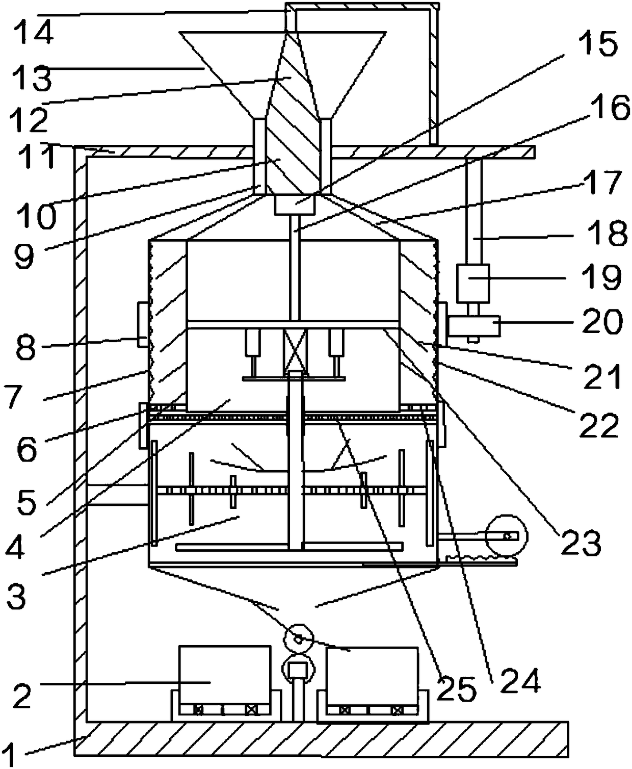
Solid and liquid chemical raw material mixing tank

A raw material mixing tank and liquid chemistry technology, which is applied in mixers, chemical instruments and methods, chemical/physical processes, etc., can solve the problems of uncoordinated mixing ratio, poor mixing effect, waste of manpower and material resources, etc., and reduce the cost of equipment The effect of using, mixing evenly and saving labor

Pending Publication Date: 2018-06-12
TIANJIN XINYUAN GUANGTAI NEW MATERIAL TECH CO LTD
View PDF0 Cites 5 Cited by
  • Summary
  • Abstract
  • Description
  • Claims
  • Application Information

AI Technical Summary

Problems solved by technology

[0002] The mixing tank is a commonly used equipment for mixing various materials. For different mixtures, different mixing reactions will occur. Some will generate heat during the mixing process, and some mixing ingredients will have larger particles, resulting in uneven mixing. However, the existing The mixing device is highly versatile, ignoring the occurrence of some detailed reactions, and then affecting the effect of the product after stirring. For the mixing of solid-liquid chemical raw materials, it is often easy to cause larger solid particles, higher liquid viscosity, and easy sticking. Attached to the inner wall, the mixing ratio is not coordinated, the mixing effect is poor, and the waste rate of the mixed product is increased. Special equipment is often required for solid crushing, and corresponding equipment is used to repeatedly clean the inner wall liquid during mixing. The process of this method is more cumbersome, and more equipment is used, resulting in waste of manpower and material resources, and higher processing costs

Method used


Image

  • Solid and liquid chemical raw material mixing tank
  • Solid and liquid chemical raw material mixing tank
  • Solid and liquid chemical raw material mixing tank

Examples


Embodiment Construction

[0027] It should be noted that, in the case of no conflict, the embodiments of the present invention and the features in the embodiments can be combined with each other.

[0028]In describing the present invention, it should be understood that the terms "center", "longitudinal", "transverse", "upper", "lower", "front", "rear", "left", "right", " The orientations or positional relationships indicated by "vertical", "horizontal", "top", "bottom", "inner" and "outer" are based on the orientations or positional relationships shown in the drawings, and are only for the convenience of describing the present invention and Simplified descriptions, rather than indicating or implying that the device or element referred to must have a particular orientation, be constructed and operate in a particular orientation, and thus should not be construed as limiting the invention. In addition, the terms "first", "second", etc. are used for descriptive purposes only, and should not be understood a...


PUM

PropertyMeasurementUnit
Angleaaaaaaaaaa

Abstract

The invention provides a solid and liquid chemical raw material mixing tank which comprises an L-shaped support. A cross plate is arranged at the top of the L-shaped support, a feeding hopper penetrates the cross plate arranged at the top of the L-shaped support, a material distributing shaft is arranged at an inner axis center of the feeding hopper, an annular pipe is placed at the bottom of thefeeding hopper, a plurality of material distributing pipes are distributed on the upper periphery of a material guide cavity, a crushing cylinder is arranged at one end, far away from the feeding hopper, of the annular pipe, a crushing shaft is concentrically, reversely and rotatably connected into the crushing cylinder, a cross rod is connected on the inner wall of the crushing shaft, a stirringmechanism is rotatably connected at the bottom of the crushing cylinder, and a quantitative discharging mechanism is arranged at an outlet corresponding to the stirring mechanism. By simple structuralmatching, a special mixing tank for solid and liquid chemical raw materials is implemented, the size uniformity of solid particles is ensured, the solid particles and liquid can be sufficiently mixed, discharging is stable, processing efficiency is improved, device use is decreased, processing cost is reduced, the working efficiency of workers is improved, mixing quality is better, and market competitiveness is improved.

Description

technical field [0001] The invention belongs to the field of mixing tanks, in particular to a mixing tank for solid-liquid chemical raw materials. Background technique [0002] The mixing tank is a commonly used equipment for mixing various materials. For different mixtures, different mixing reactions will occur. Some will generate heat during the mixing process, and some mixing ingredients will have larger particles, resulting in uneven mixing. However, the existing The mixing device is highly versatile, ignoring the occurrence of some detailed reactions, and then affecting the effect of the product after stirring. For the mixing of solid-liquid chemical raw materials, it is easy to cause larger solid particles, higher liquid viscosity, and easy sticking. Attached to the inner wall, the mixing ratio is not coordinated, the mixing effect is poor, and the waste rate of the mixed product is increased. Special equipment is often required for solid crushing, and corresponding eq...

Claims


Application Information

Patent Timeline
IPC IPC(8): B01F13/10B01F15/00B01F15/02
CPCB01F33/833B01F33/86B01F35/2211B01F35/187B01F35/717B01F35/71731B01F35/7547
Inventor 沈迎迎赵林桂张磊
Owner TIANJIN XINYUAN GUANGTAI NEW MATERIAL TECH CO LTD
Learn More