Valve manifold serially mounted to distributed control system assembly

A distributed control and control system technology, applied in general control systems, control/regulation systems, program control, etc., can solve expensive and labor-intensive problems

Active Publication Date: 2018-06-08
NUMATICS INCORPORTED
View PDF5 Cites 0 Cited by
  • Summary
  • Abstract
  • Description
  • Claims
  • Application Information

AI Technical Summary

Problems solved by technology

However, this method of connection is expensive and labor-intensive, requiring a separate CHARM I / O module with its own microprocessor to be connected to each solenoid valve of each valve station on the manifold

Method used


Image

  • Valve manifold serially mounted to distributed control system assembly
  • Valve manifold serially mounted to distributed control system assembly
  • Valve manifold serially mounted to distributed control system assembly

Examples


Embodiment Construction

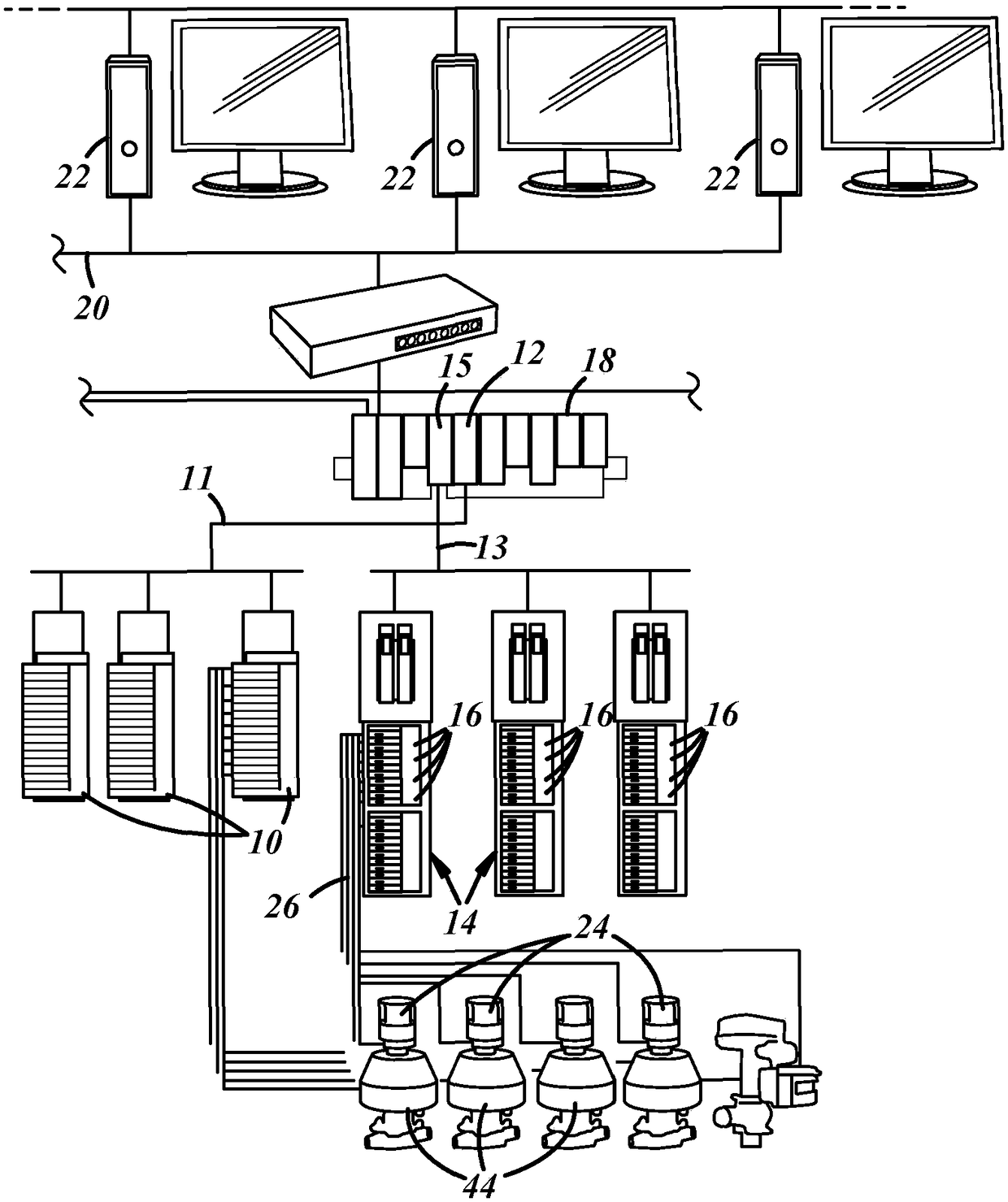
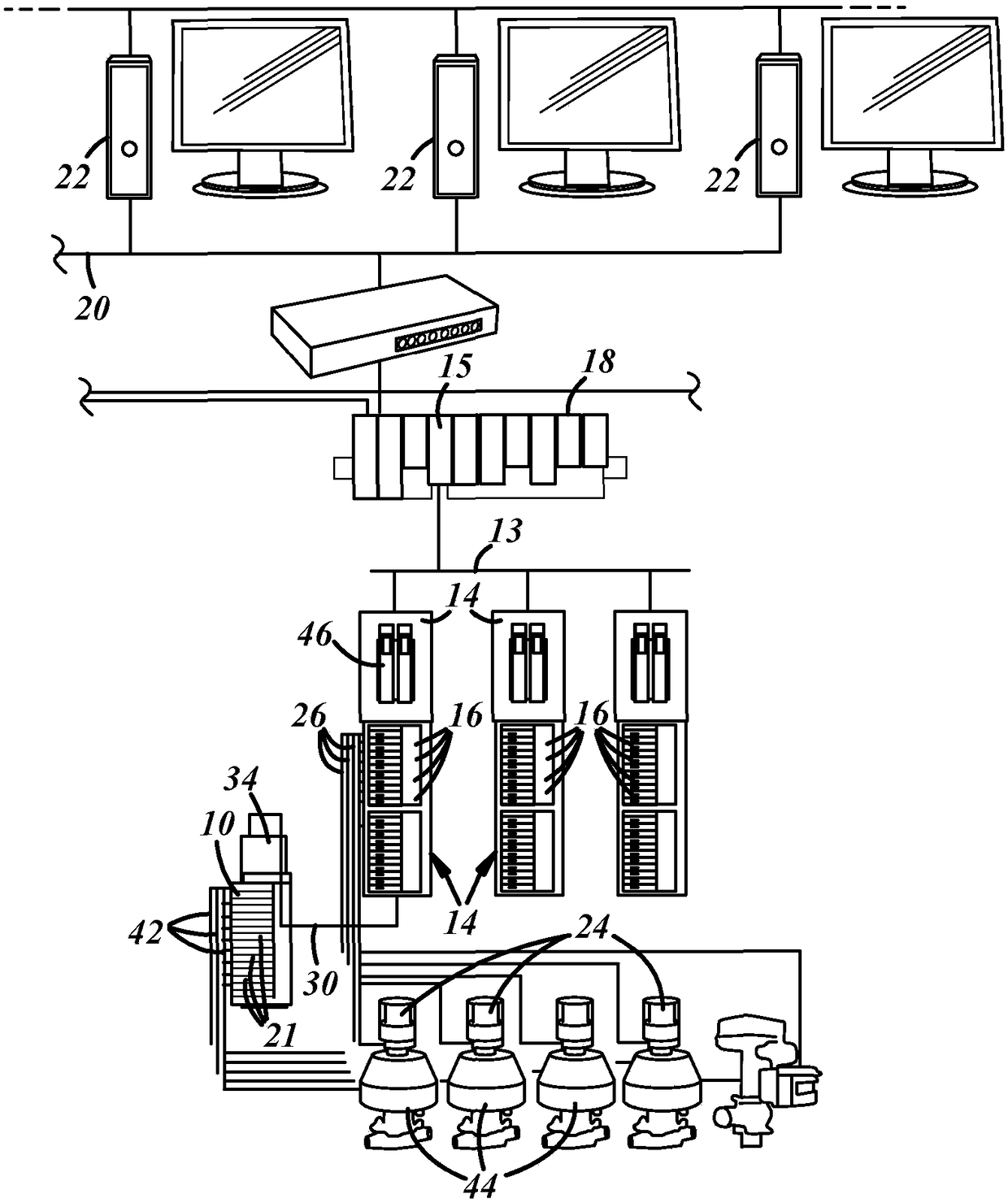
[0024] now refer to figure 2 , the control network 20 has a plurality of workstations 22 connected to the DCS 18 . The DCS may be the commercially available DELTAV from Emerson Process Management TM system. The DCS 18 is in turn connected through its network 13 to one or more I / O banks 14 comprising individual input / output modules 16 . A suitable I / O set may be the commercially available CHARM from Emerson Process Management TM I / O group. These I / O banks 14 may be located remotely from the DCS 18 .

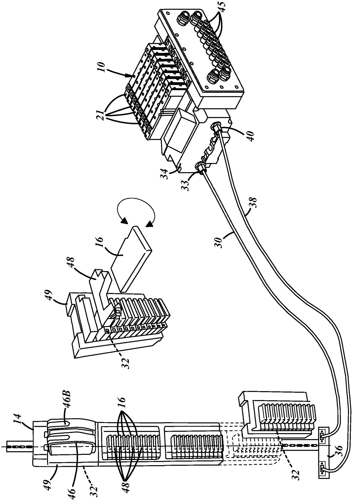
[0025] A number of individual I / O modules 16 in a group may be connected to field sensors 24 by cables 26 for receiving information from field sensors 24 . Additionally, valve manifold 10 may also be connected to I / O bank 14 . Preferably, as image 3 As shown, this connection is made by extending a cable 30 integrating both power and communication from a backplane 32 of the I / O pack 14 to a communication fitting 33 of a communication module 34 of the valve manifold 10 . M...


PUM


Abstract

A control system has an I / O bank with a communication module controlling a plurality of Input / Output modules operably connected to its communication backplane and a valve manifold having a communication module serially connected to the backplane of the I / O bank. The I / O bank with a plurality of Input / Output modules is constructed to be connected to a plurality of field sensors or loads. The valvemanifold with a plurality of solenoid valves is constructed to be pneumatically connected to a plurality of field devices.

Description

technical field [0001] The field of the invention relates to an electrical bus system having a solenoid valve manifold connected in series to a distributed control system via a distributed I / O system. Background technique [0002] Industrial automation uses many control devices. One useful control device is a solenoid valve manifold, often simply called a valve manifold, which houses a plurality of electrically actuated solenoid valves. Solenoid valves control the direction of hydraulic or pneumatic flow for actuating other downstream field devices, such as process valves. These valve manifolds have a communication module that is usually installed near the solenoid valve station and connected to various fieldbus networks. [0003] These fieldbus networks have become commonplace in automation control. A fieldbus network provides remote control of the valve station. A typical fieldbus network might use EtherNet / IP TM , FIPIO TM , Interbus-S TM 、ControlNet TM 、DeviceNet...

Claims


Application Information

Patent Timeline
Patent Type & Authority Applications(China)
IPC IPC(8): H05K7/14
CPCH05K7/1467G05B19/054G05B19/0423H05K7/1479G05B19/44
Inventor 恩里科·德·卡罗利斯约翰·F·埃斯丘格雷戈里·A·韦尔斯
Owner NUMATICS INCORPORTED
Why Eureka
Try Eureka