
Valve device for throttling a pressure medium flow, and damping device for damping pressure pulsations

A technology of pressure medium and shock absorbing device, which is applied in the direction of valves absorbing fluid energy, valve devices, brakes, etc., which can solve the problems of high manufacturing cost of valve devices, sensitivity to viscosity fluctuations, etc., and achieve the effect of improving the throttling effect

Active Publication Date: 2018-06-08
ROBERT BOSCH GMBH
View PDF7 Cites 5 Cited by
  • Summary
  • Abstract
  • Description
  • Claims
  • Application Information

AI Technical Summary

Problems solved by technology

[0007] The disadvantage is that a valve arrangement with a laterally arranged outlet is more expensive to manufacture and reacts more sensitively to fluctuations in the viscosity of the pressure medium due to deflections of the pressure medium, thus having a greater Wider diffuse throttling characteristics

Method used


Image

  • Valve device for throttling a pressure medium flow, and damping device for damping pressure pulsations
  • Valve device for throttling a pressure medium flow, and damping device for damping pressure pulsations
  • Valve device for throttling a pressure medium flow, and damping device for damping pressure pulsations

Examples


Embodiment Construction

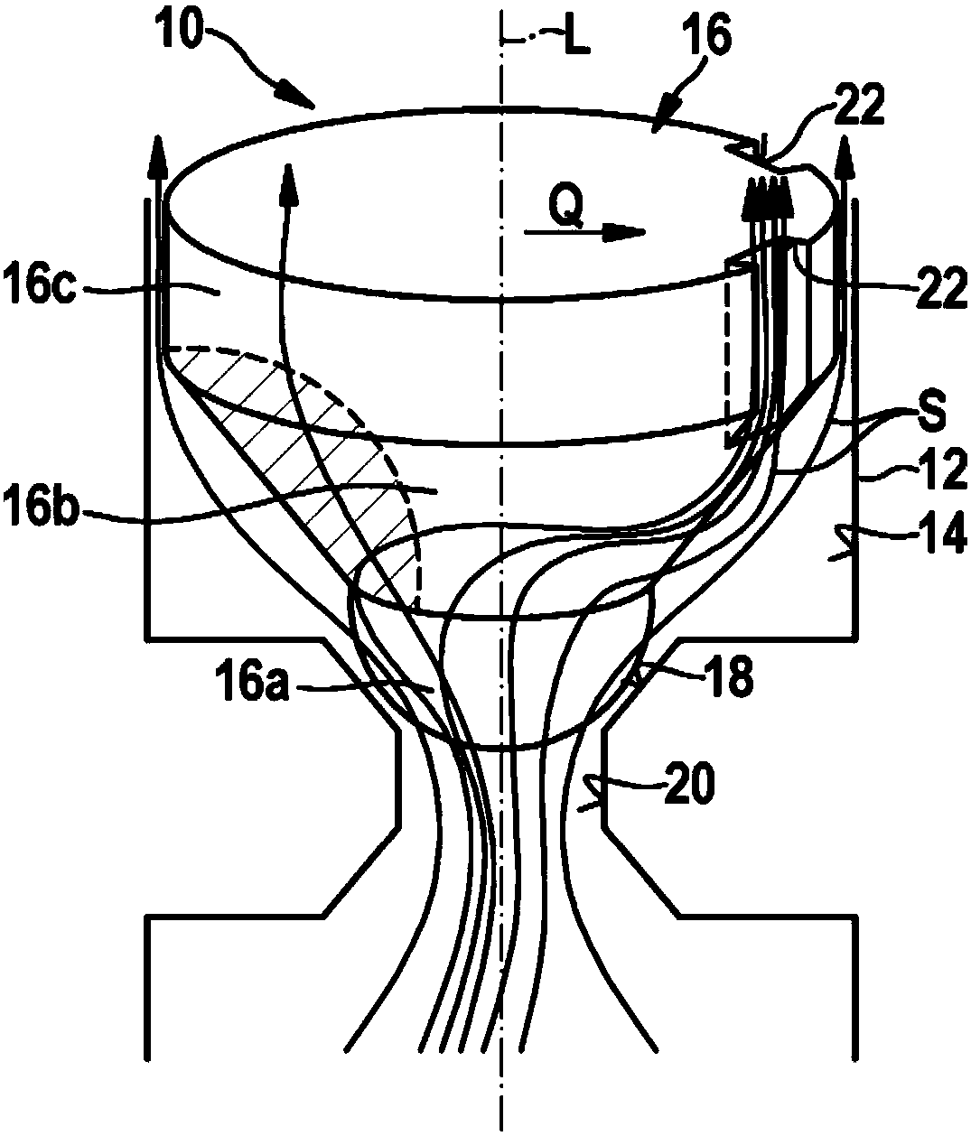
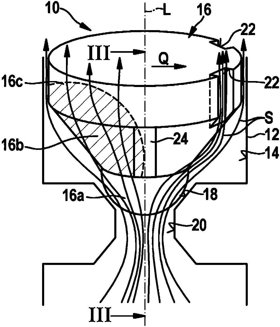
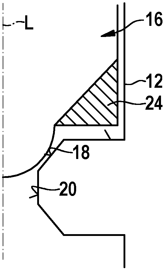
[0018] figure 1 The illustrated valve device 10 consists of a valve body 12 , which is formed with a valve bore 14 , and a valve member 16 , in which the valve member is accommodated so as to be displaceable in the axial direction. The valve bore 14 is offset once inwards on its inner diameter and forms a valve seat 18 around a throttle cross section 20 . The valve seat 18 is formed, for example, as an inner cone, but it can also be embodied as right-angled or rounded.

[0019] As indicated by the drawn flow arrow S, the pressure medium is based on figure 1 The illustration in , flows through the throttle cross-section 20 from bottom to top. The valve member 16 is thus arranged downstream of the throttle cross section 20 in the valve bore 14 . In the shown flow state of the valve device 10 , the valve member 16 is lifted from the throttle cross section 20 , so that the valve member 16 is surrounded by pressure medium over its entire circumference. The outlet of the valve d...


PUM


Abstract

The invention is based on a valve device (10) with a valve body (12) forming a throttle cross section (20) and with a valve element (16) setting the throttle cross section (20) depending on the pressure. To avoid pulsation-induced noises, it is proposed to equip the valve element (16) with flow-deflecting means (22; 24) which cause action upon the valve element (16) with a transverse force (Q). Said means prevent noise-causing vibrations of the valve element (16) and permit a lower throttling effect of the valve device (10), in particular when volumetric flows are increased. The invention furthermore relates to a damping device (50), in particular for damping pressure pulsations in a brake circuit of a slip-controllable vehicle brake system.

Description

technical field [0001] The invention relates to a valve arrangement according to the features of the preamble of claim 1 and to a damping arrangement according to the features of the preamble of claim 9 . Background technique [0002] Current skid-controllable vehicle braking systems provide additional functions such as assisting the driver in maintaining distance from the vehicle in front. This takes place by means of an active intervention in the brake system in that it builds up brake pressure on the wheel brakes without the driver himself having to actuate the brake pedal. So that the driver does not experience disturbing noises in this situation, shock absorbers are used that dampen pressure pulsations caused by the brake system pressure generator. [0003] The damping device consists of a fluid resistance and a fluid capacity, which is connected into the hydraulic circuit upstream of the fluid resistance. For the effectiveness of the shock absorber, a large throttlin...

Claims


Application Information

Patent Timeline
Patent Type & Authority Applications(China)
IPC IPC(8): B60T17/04F16K1/12F16K1/14F16K1/38
CPCB60T17/04F16K1/14F16K1/38F16K25/02F16K47/04B60Y2400/81Y10T137/785B60T15/00B60T2270/10F16K47/16
Inventor J·诺伯格P·谢林杰A·莱希勒
Owner ROBERT BOSCH GMBH
Learn More