Dialysis system and method including flow path insulator

A technology of insulators and flow paths, used in dialysis systems, drug devices, other medical devices, etc., can solve problems such as electrical failures

Active Publication Date: 2018-06-08
GAMBRO LUNDIA AB
View PDF5 Cites 0 Cited by
  • Summary
  • Abstract
  • Description
  • Claims
  • Application Information

AI Technical Summary

Problems solved by technology

Electrical components present a risk of electrical failure

Method used


Image

  • Dialysis system and method including flow path insulator
  • Dialysis system and method including flow path insulator
  • Dialysis system and method including flow path insulator

Examples


Embodiment Construction

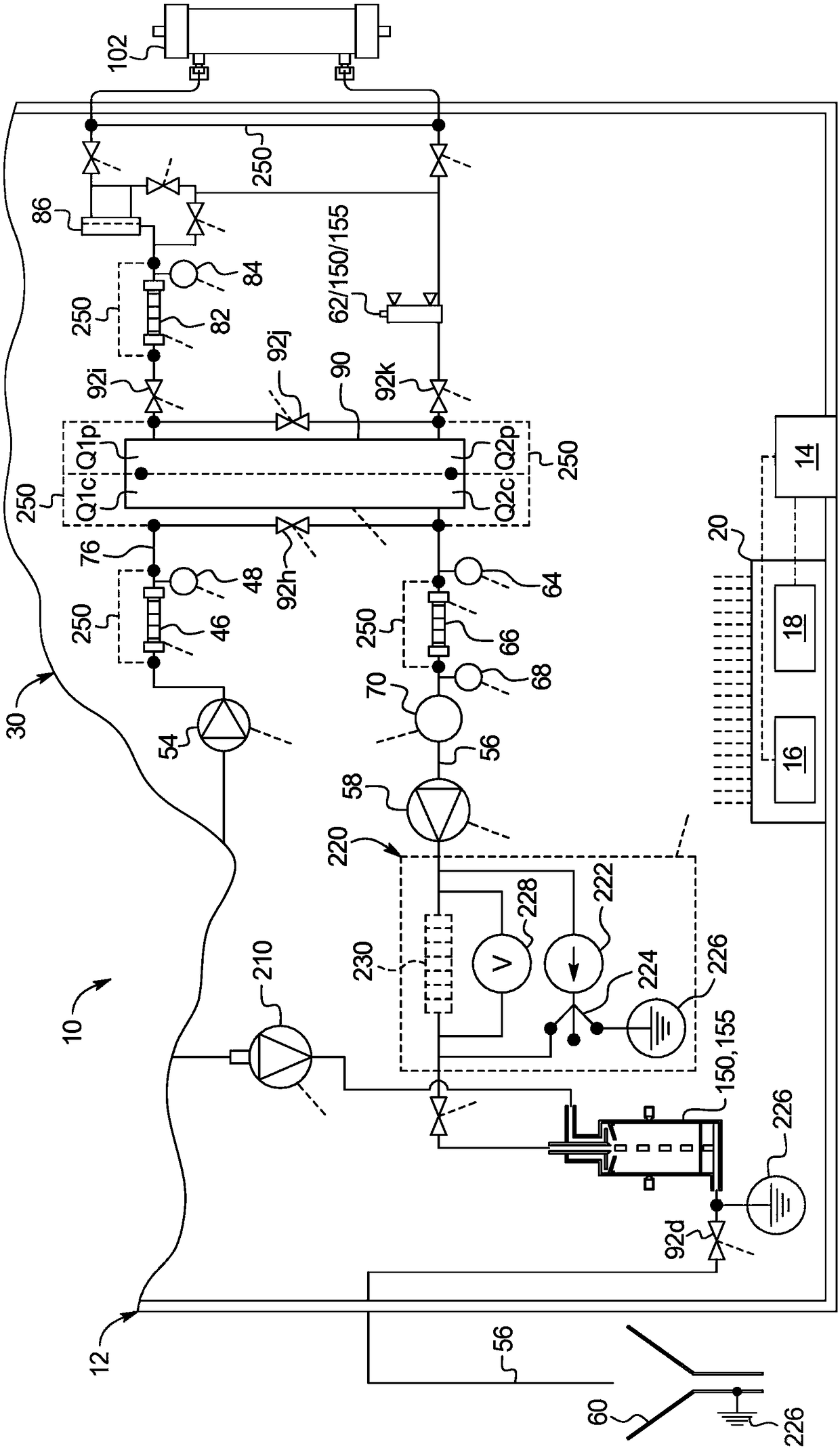
[0078] Referring now to the drawings, in particular to FIG. 1 and figure 2 , an embodiment of the disclosed system is illustrated by system 10 . System 10 includes a machine 12 having an enclosure or housing. The housing of the machine 12 holds the contents of the dialysate or dialysate circuit 30 described in detail below. The housing of the machine 12 also supports a user interface 14 that allows a nurse or other operator to interact with the system 10 . The user interface 14 may have a monitor screen operable with a touchscreen overlay, electromechanical buttons (eg, membrane switches), or a combination of both. User interface 14 is in electrical communication with at least one processor 16 and at least one memory 18 . The at least one processor 16 and at least one memory 18 also electronically interact with and, where appropriate, control the pumps, valves and sensors described herein, such as those of the dialysate circuit 30 . At least one processor 16 and at least ...


PUM


Abstract

A renal failure therapy system (10) includes: a dialyzer (102); a blood circuit (100) including a blood pump (120) in fluid communication with the dialyzer (102); a dialysis circuit (30) in fluid communication with the dialyzer (102); and at least one flow path insulator (150, 155) located in the dialysis circuit (30) or the blood circuit (100), the flow path insulator (150, 155) including a structure that separates liquid flowing within the flow path insulator (150, 155) into a plurality (e.g., two or more) of separated liquid segments (160) that create electrical isolation within the flow path insulator (150, 155).

Description

technical field [0001] The present disclosure generally relates to medical devices. More specifically, the present disclosure relates to electrical insulation of medical devices. Background technique [0002] Hemodialysis ("HD") typically uses diffusion to remove waste products from a patient's blood. Diffusion is caused by a diffusion gradient that occurs across a semipermeable dialyzer between blood and an electrolyte solution called dialysate. Hemofiltration ("HF") is another renal replacement therapy that relies on the convective transport of toxins from the patient's blood. This therapy is achieved by adding replacement fluid (typically 10 to 90 liters of such fluid) to the extracorporeal circuit during treatment. During HF therapy, the patient's accumulated replacement fluid and fluids between treatments are ultrafiltered, thereby providing a convective delivery mechanism, which is particularly beneficial for the removal of medium and large molecules (in hemodialysi...

Claims


Application Information

Patent Timeline
IPC IPC(8): A61M1/16A61M1/34A61M1/36
CPCA61M1/3413A61M1/3621A61M1/16A61M2205/3331A61M2205/3334A61M2205/07A61M2205/3368A61M2205/3306A61M2205/3372A61M2205/70A61M2205/15A61M1/34A61M1/367A61M1/14A61M2206/14
Inventor 斯特乌勒·霍博若奥洛夫·杨松E·托里尼P·森德柳斯I·帕尔松D·斯塔尔
Owner GAMBRO LUNDIA AB
Why Eureka
Try Eureka