
Electrode for brain wave measurement

An electrode and brain wave technology, applied in the field of electrodes for brain wave measurement, can solve problems such as troublesome work, achieve the effects of lightening the burden, high sensitivity, and ensuring the contact area

Inactive Publication Date: 2018-06-08
NITTA CORP
View PDF2 Cites 2 Cited by
  • Summary
  • Abstract
  • Description
  • Claims
  • Application Information

AI Technical Summary

Problems solved by technology

Conductive paste has the function of fixing the position of the measurement site in addition to reducing the contact resistance between the scalp and the electrode, but it is troublesome to remove it after measurement

Method used


Image

  • Electrode for brain wave measurement
  • Electrode for brain wave measurement
  • Electrode for brain wave measurement

Examples


Embodiment Construction

[0034] Hereinafter, embodiments of the present invention will be described in detail with reference to the accompanying drawings.

[0035] 1. Overall structure

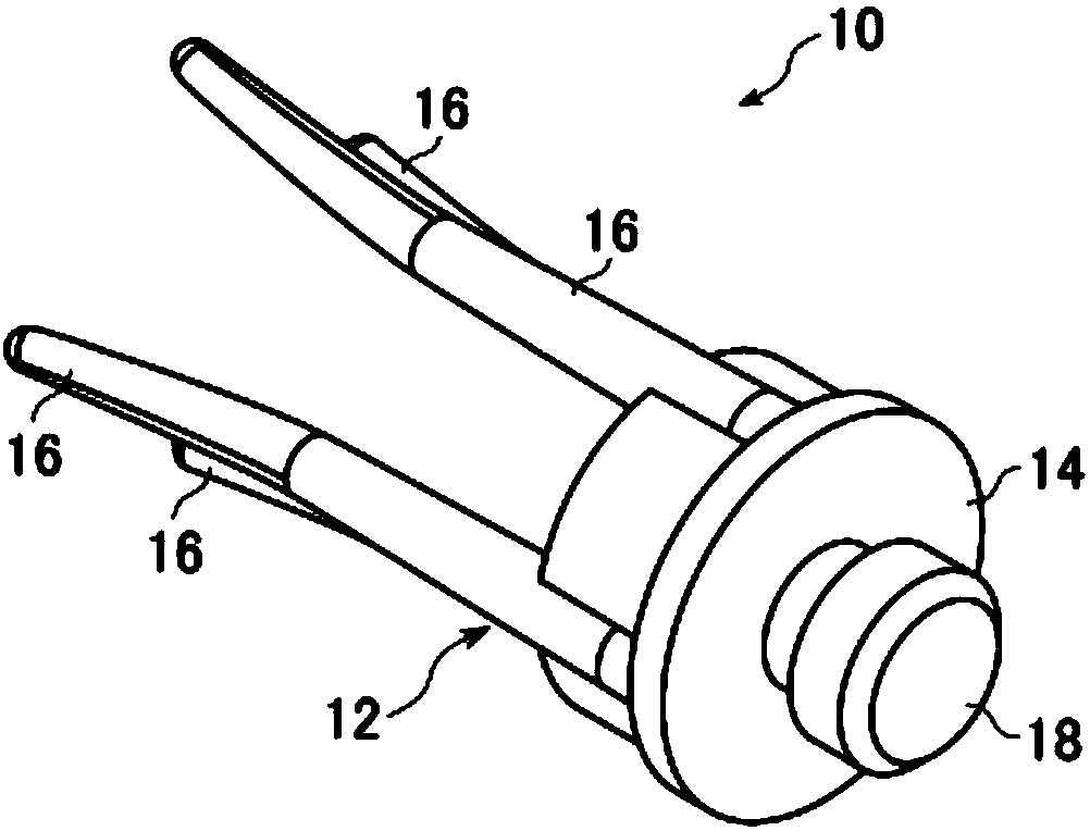
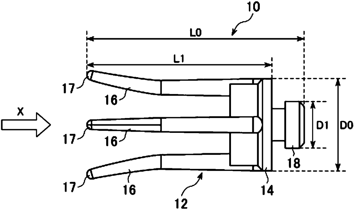
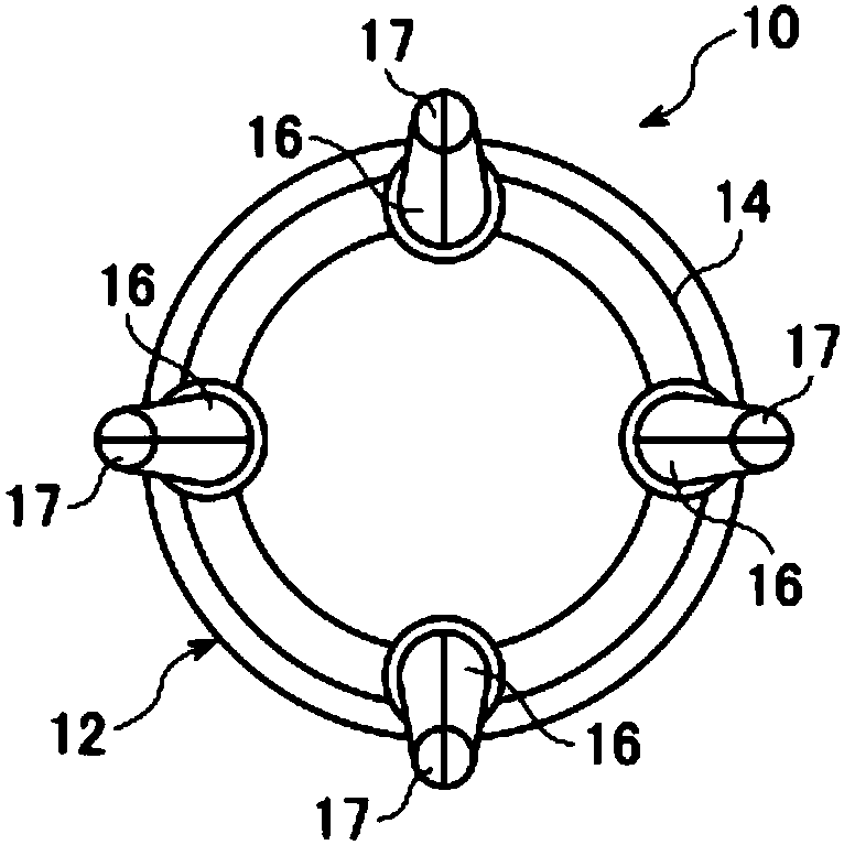
[0036] like figure 1 As shown, the electroencephalogram measurement electrode 10 includes a base material 12 made of an elastic body, and the base material 12 includes a support portion 14 and a tilt portion 16 formed to protrude from one surface of the support portion 14 . A structure not shown is formed on the surface of the tilting portion 16 . In the present embodiment, the structure is not formed inside the tilting portion 16 of the base material 12, but is exposed on the surface. Since this structure has electrical conductivity, the surface of the tilting portion 16 has electrical conductivity. With this structure, a conductive path is formed in the base material 12 . In addition, a connection protrusion 18 is formed on the other surface of the support portion 14 on the opposite side to the tilting portion 1...


PUM


Abstract

An electrode (10) for brain wave measurement is provided with a base member (12), which comprises an elastic body, and a structure formed on the base member (12). The electrode (10) for brain wave measurement is characterized in that the base member (12) comprises a support part (14) and an elastically-deformable tilting part (16) formed so as to project from one surface of the support part (14).The electrode (10) for brain wave measurement is further characterized in that the structure is formed on a surface of the tilting part (16) and contains multiple nanocarbon members that form an interconnected network structure and are fixed to the base member (12).

Description

technical field [0001] The present invention relates to an electrode for brain wave measurement. Background technique [0002] As a conventional electroencephalogram measurement electrode, a type in which a conductive paste is inserted between the subject's scalp and the electrode is widely used. In addition to reducing the contact resistance between the scalp and the electrode, the conductive paste has the function of fixing the position of the measurement site, but it needs to be removed after the measurement, which brings trouble to the operation. [0003] Therefore, in recent years, an electrode (dry electrode) capable of ensuring low contact resistance without using a conductive paste has been developed. As dry electrodes, for example, a multi-pin type dry electrode attached to a hair band and used (eg, Non-Patent Document 1) and a multi-pin type dry electrode attached to a headgear (eg, Non-Patent Document 2) have been proposed. In these dry electrodes, the multi-lea...

Claims


Application Information

Patent Timeline
Patent Type & Authority Applications(China)
IPC IPC(8): A61B5/0408A61B5/0492A61B5/0478A61B5/296
Inventor 森本梓奥井敬造
Owner NITTA CORP
Learn More