
Device for testing the visual behavior of a person, and method for determining at least one optical design parameter of an ophthalmic lens using such a device

A technology for testing equipment and visual behavior. It is applied in the fields of testing eye equipment, optics, and medical science. It can solve the problems of wearers customizing gradient ophthalmic lenses, inaccurate visual testing equipment, and suboptimal optical design of gradient lenses.

Active Publication Date: 2018-06-08
ESSILOR INT CIE GEN DOPTIQUE
View PDF11 Cites 1 Cited by
  • Summary
  • Abstract
  • Description
  • Claims
  • Application Information

AI Technical Summary

Problems solved by technology

[0010] Therefore, vision testing equipment is inaccurate and the optical design parameters determined by the optician therefore do not always represent the visual behavior of the individual under natural conditions
[0011] As a result, the optical design of the progressive lens is not optimal, and it may therefore be difficult to customize the progressive ophthalmic lens to the wearer

Method used


Image

  • Device for testing the visual behavior of a person, and method for determining at least one optical design parameter of an ophthalmic lens using such a device
  • Device for testing the visual behavior of a person, and method for determining at least one optical design parameter of an ophthalmic lens using such a device
  • Device for testing the visual behavior of a person, and method for determining at least one optical design parameter of an ophthalmic lens using such a device

Examples


Embodiment Construction

[0062] By way of introduction, it will be noted that identical or similar elements of the different embodiments shown in the various figures will be referred to with the same reference numerals and will not be described every time.

[0063] It should also be noted that in the ensuing disclosure, the terms "top" (or "upper") and "bottom" (or "lower") will be used relative to the individual using the test device, with top referring to the part turned toward the individual's head. This side, and bottom refers to the side turned towards the individual's feet.

[0064] Likewise, the term "anterior" refers to the side turned toward the individual, and the term "posterior" refers to the side opposite the anterior side.

[0065] figure 1 Individual 1 is shown whose visual behavior needs to be tested.

[0066] For this purpose, the individual 1 holds in his hand 2 a testing device 10 according to the invention intended to determine this visual behavior under given conditions.

[006...


PUM


Abstract

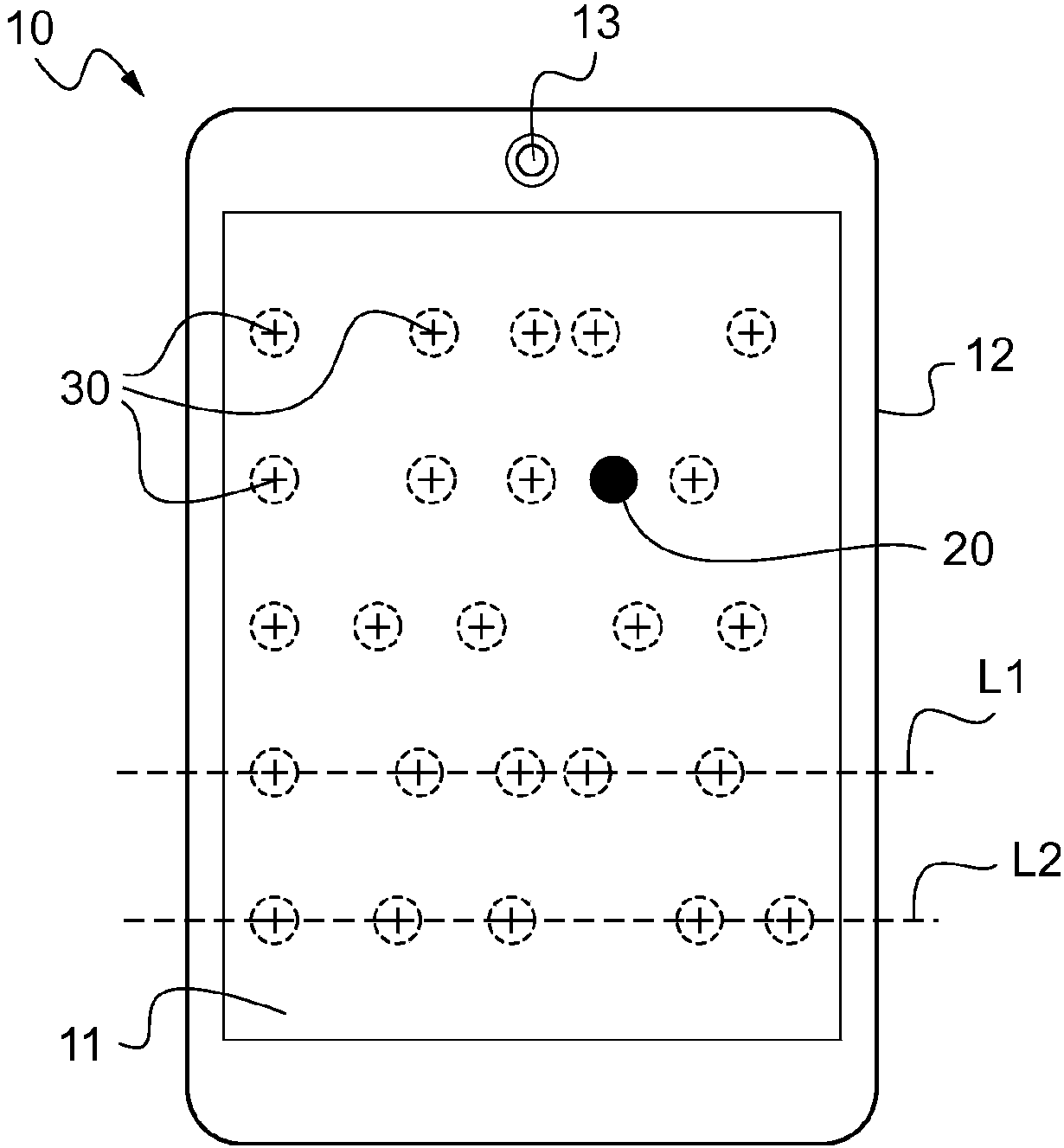
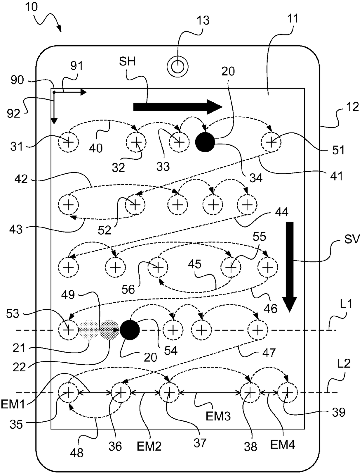
The invention relates to a device (10) for testing the visual behavior of a person. Said device comprises: an active display (11) capable of displaying at least one visually dominant target (20) in aplurality of positions (30) that are variable over time and that are aligned along at least one line (L1, L2) or column, and a unit for controlling the display. Said unit is programmed so that the consecutive display positions of the target follow, over time, a visual tracking protocol.

Description

technical field [0001] The present invention generally relates to a testing device allowing the visual behavior of an individual to be determined. [0002] The invention also relates to a method of using such a device to determine at least one optical parameter for designing an ophthalmic lens. Background technique [0003] Even more precise personalization of ophthalmic lenses of frames intended to equip individuals to correct their vision requires increased knowledge of the individual's visual behavior under vision conditions that are natural and representative of actual use of the ophthalmic lenses. [0004] Determining the individual's visual behavior parameters then allows improving the optical design of the ophthalmic lens to be mounted in the spectacle frame. [0005] In particular, during the optical design of progressive ophthalmic lenses, it is particularly important to have relevant optical design data to take into account how these lenses are used at near vision...

Claims


Application Information

Patent Timeline
Patent Type & Authority Applications(China)
IPC IPC(8): A61B3/024A61B3/032A61B3/113G02C13/00
CPCA61B3/024A61B3/032A61B3/113G02C13/005G02C7/025A61B3/0041A61B3/0091A61B3/145
Inventor G·埃斯卡利耶I·普莱恩B·卢梭
Owner ESSILOR INT CIE GEN DOPTIQUE
Learn More