
Probe polarization rotation device, electromagnetic field sampling system and electromagnetic field sampling method

A polarization rotation and sampling system technology, applied in the fields of electromagnetic field characteristics, measuring devices, and measuring electrical variables, can solve problems such as slow acquisition speed, performance, and parameter differences, and achieve improved accuracy, increased sampling speed, and accurate sampling results Effect

Pending Publication Date: 2018-06-08
SUNYIELD TECH CO LTD
View PDF10 Cites 3 Cited by
  • Summary
  • Abstract
  • Description
  • Claims
  • Application Information

AI Technical Summary

Problems solved by technology

The most conventional method is to use a single dual-polarization probe to detect and sample the electromagnetic field. The working principle can refer to the electromagnetic field near-field scanning device and scanning method disclosed in the Chinese invention patent with the publication number CN103941106A. The problems with this measurement method are , if the electromagnetic field is relatively large and there are many points to be collected, the entire collection speed will be very slow
[0003] In addition, the polarization probe is composed of copper-copper sulfate reference electrode and the surrounding carbon steel plate and salt bridge. In the same polarization of the polarization probe, the composition of different parts will have certain deviations. , if the electric field probe is a dual-polarization probe, the difference in composition between the two polarizations will be even greater, that is, there are differences in performance and parameters between the two polarizations of the dual-polarization probe, which leads to the use of a dual-polarization probe There is a large difference in sampling the two polarizations, making the measurement results not very accurate

Method used


Image

  • Probe polarization rotation device, electromagnetic field sampling system and electromagnetic field sampling method
  • Probe polarization rotation device, electromagnetic field sampling system and electromagnetic field sampling method
  • Probe polarization rotation device, electromagnetic field sampling system and electromagnetic field sampling method

Examples


Embodiment 1

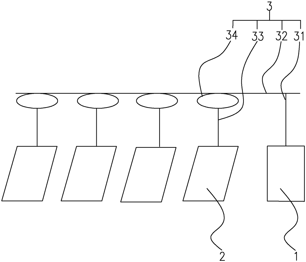
[0037] Such as figure 1 As shown, a probe polarization rotation device is based on the use of a single polarization probe 2 to complete the measurement of the horizontal and vertical components of the electromagnetic field, including a power unit 1 (the present invention uses a rotary drive motor) for providing rotational power; Polarization probe 2, set 4-8, and the initial polarization setting direction is the same; transmission unit 3, used to apply the force provided by the power unit 1 to the single-polarization probe 2, so that each single-polarization probe 2 completes Synchronized rotation of polarization. The transmission unit 3 includes a power connector 31 , a transmission member 32 , a probe bracket 33 , and a probe connector 34 which are sequentially connected in linkage. The transmission member 32 is a straight rod, and the plurality of single-polarization probes 2 are linearly distributed along the axial direction of the straight rod, and are mainly used for tw...

Embodiment 2

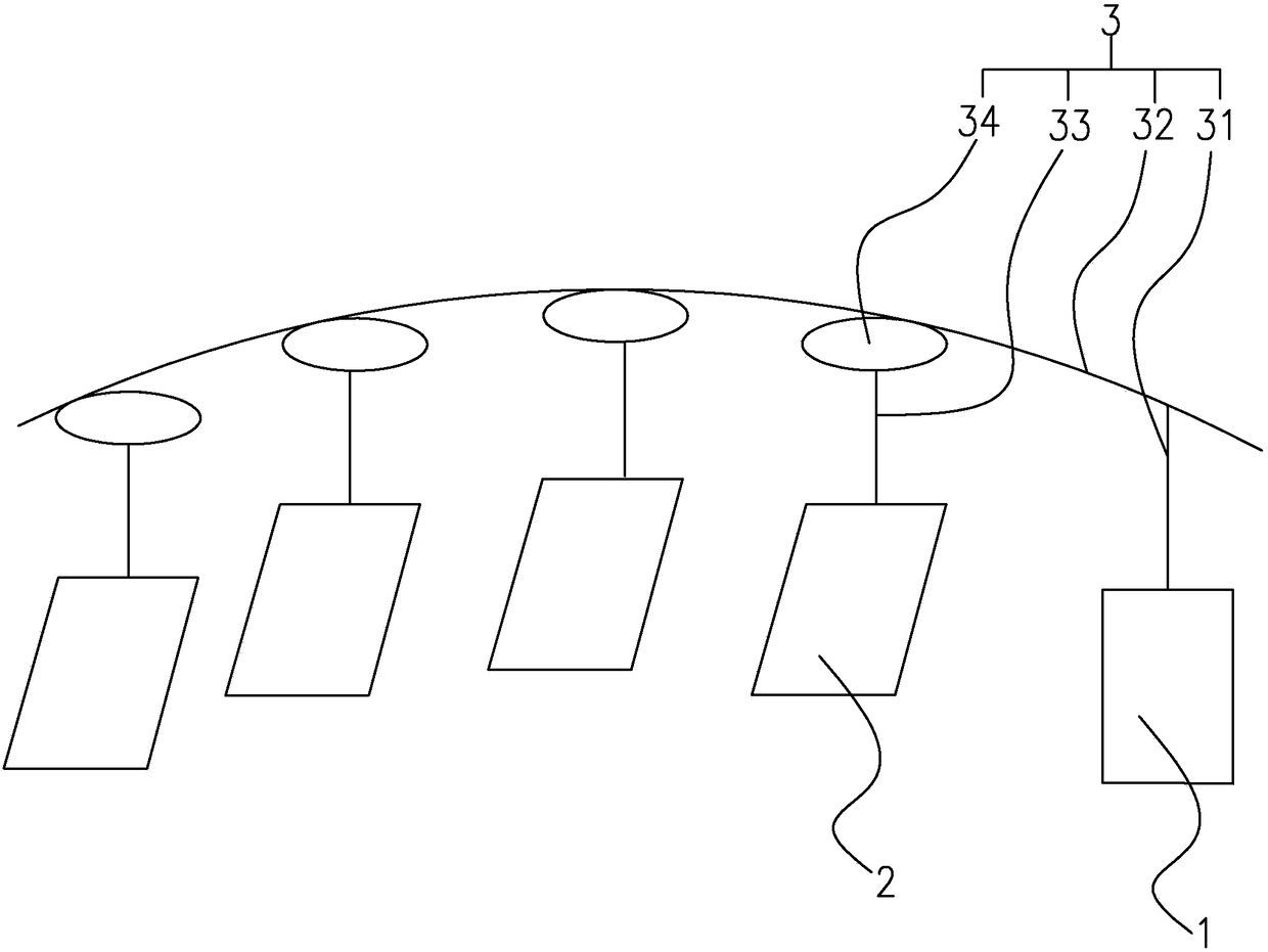
[0039] Such as figure 2 As shown, different from Embodiment 1, the transmission member 32 is an arc rod, and the plurality of single-polarization probes 2 are distributed in a radian along the curved track of the arc rod, and are mainly used for detecting electromagnetic waves in a spherical field. The detection and collection of two mutually perpendicular polarization components.

Embodiment 3

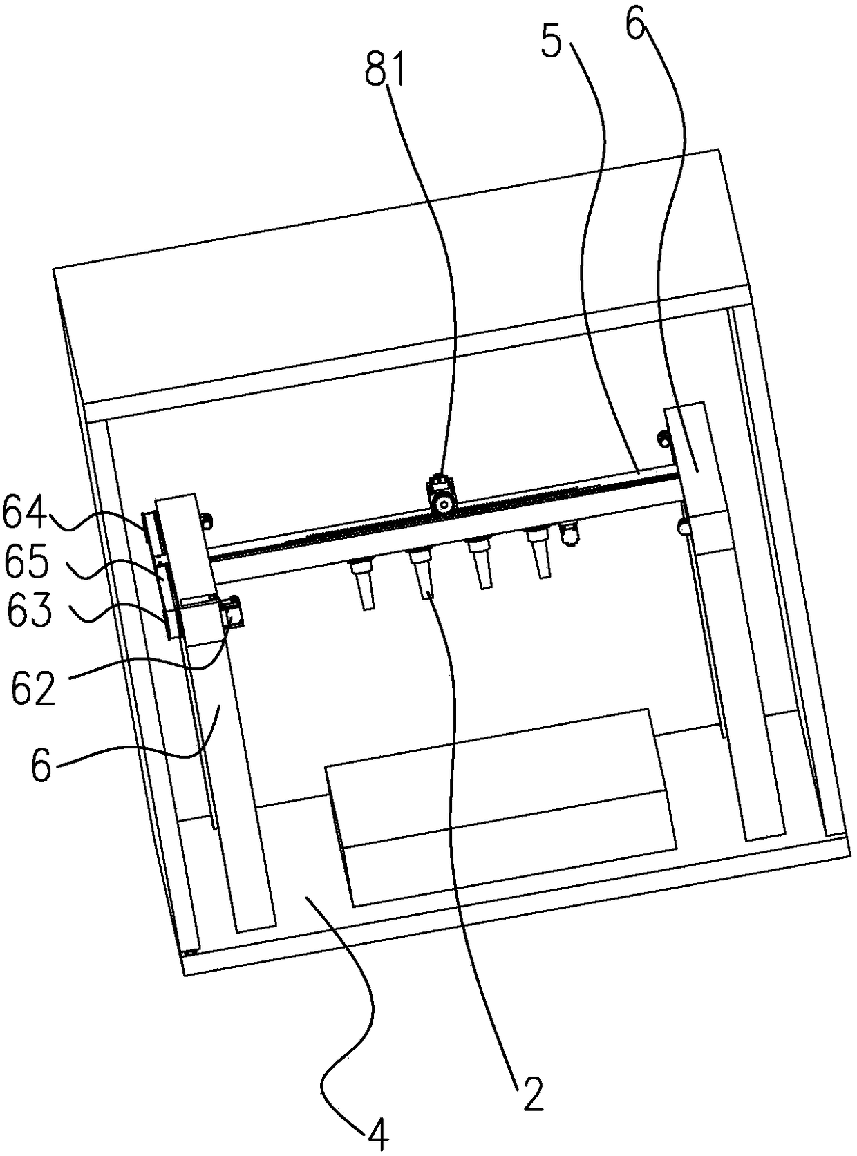
[0041] Such as image 3 , 4 As shown, the electromagnetic field sampling system includes a base (which can be the entire closed dark room, or only a base in the installation), left and right guide rails 5 fixedly arranged on the base, and two front and rear guide rails 6 parallel to each other. The two ends of the left and right guide rails 5 are respectively fixed on the two front and rear guide rails 6. In the probe polarization rotation device described in Embodiment 1, the probe polarization rotation device is integrally arranged on the left and right guide rails 5 and can be left and right along the left and right guide rails 5. slide.

[0042]Wherein, the concrete structure that the left and right guide rails 5 slide forward and backward along the front and rear guide rails 6 is:

[0043] Two front and rear guide rails 6 are respectively arranged on the two ends of the left and right guide rails 5, and the top of the front and rear guide rails 6 is provided with a fron...


PUM


Abstract

The invention provides a probe polarization rotation device, which finishes measurement of horizontal and vertical components of an electromagnetic field through single-polarization probes, and comprises a power unit for providing rotation power; the single-polarization probes, the number of which is at least two, and the initial polarization setting directions of which are same; and drive units for acting the power provided by the power unit onto the single-polarization probes to enable the single-polarization probes to finish polarization synchronous rotation. By changing a conventional single dual-polarization probe into a plurality of single-polarization probes, sampling measurement of one component can be carried out simultaneously at multiple sampling points; through cooperative action of the added power unit and the drive units, all of the single-polarization probes are driven to rotate for 90 degrees simultaneously, and sampling measurement of another component is finished; andmeasurement of two components is finished at one sampling point in one polarization, so that measurement results of two components on the same point have no error, and sampling precision is improved.

Description

Background technique [0001] Near-field measurement is carried out with network analysis and receiving probes. In traditional near-field measurement systems, the filling to be measured is usually kept fixed, and the probe is rotated around it to obtain different plane, cylinder, and spherical field diagrams. In the spherical field, the electromagnetic wave is often represented by two mutually perpendicular polarization components E _theta, E _phi; in the plane field, it is often represented by E _x, E _y; in the cylindrical field, it is often represented by E _z, E _phi. [0002] Because two components in the electromagnetic field need to be measured, in order to describe the target electromagnetic field, the electric field probe is often used to receive the electromagnetic wave in space, sample relevant data and send it to the computer for analysis and result display. The most conventional method is to use a single dual-polarization probe to detect and sample the electromagnet...

Claims


Application Information

Patent Timeline
Patent Type & Authority Applications(China)
IPC IPC(8): G01R29/08
CPCG01R29/0878
Inventor 韩栋
Owner SUNYIELD TECH CO LTD
Learn More