Ceiling lamp connecting device

A connection device and ceiling lamp technology, applied in lighting devices, fixed lighting devices, lighting auxiliary devices, etc., can solve problems such as threats to personal safety, loose connection between the frame and the light guide plate, and difficulty in being observed by human eyes, so as to achieve enhanced stop effect, the effect of strengthening the positioning effect

Inactive Publication Date: 2018-06-08
重庆李不凡商贸有限公司
View PDF6 Cites 3 Cited by
  • Summary
  • Abstract
  • Description
  • Claims
  • Application Information

AI Technical Summary

Problems solved by technology

In daily life, the connection between the frame and the light guide plate of the ceiling light is loose due to the long use time, but it is difficult for the human eye to observe. If it cannot be dealt with in time, it will threaten personal safety at any time

Method used


Image

  • Ceiling lamp connecting device
  • Ceiling lamp connecting device

Examples


Embodiment Construction

[0017] Further detailed explanation through specific implementation mode below:

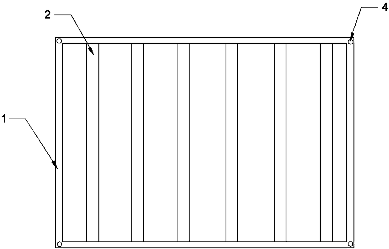
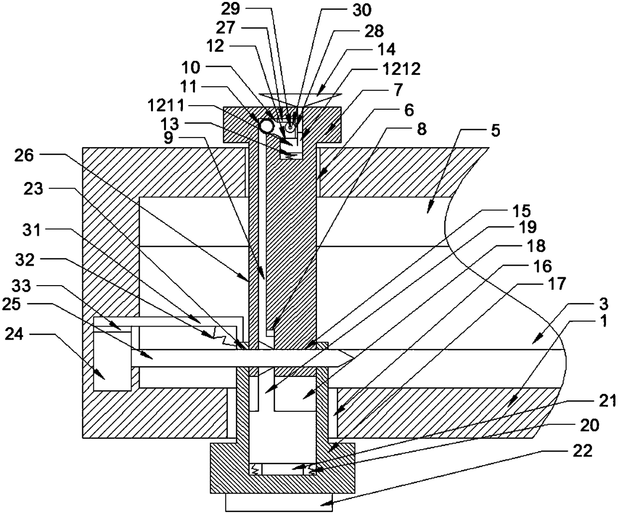
[0018] The reference signs in the drawings of the specification include: frame 1, light bar 2, light guide plate 3, hook 4, chute 5, upper hole 6, upper limit block 7, bottom hole 8, first wedge block 9, air hole 10. Air bag 11, slider 12, horizontal section 1211, vertical section 1212, first spring 13, suction cup 14, upper hole 15, lower hole 16, lower limit block 17, top hole 18, second wedge block 19 , second spring 20, trigger switch 21, reminder light 22, lower side hole 23, iron arm 24, push rod 25, through hole 26, first rack 27, second rack 28, fixed shaft 29, gear 30, Rocking arm 31, the 3rd spring 32, permanent magnet 33.

[0019] The embodiment is basically as attached figure 1 And attached figure 2 Shown: the connection device of the ceiling light, including the frame 1, the light bar 2, the light guide plate 3 and the hook 4, the light bar 2 and the hook 4 are fixed on the frame...


PUM


Abstract

The invention discloses a ceiling lamp connecting device which comprises a frame, a lamp bar, a light guiding plate and a lifting hook. A sliding groove is formed in the frame, an upper hole is formedin the top of the frame, an upper limiting block is in sliding connection with the upper hole, a bottom hole is formed in the bottom of the upper limiting block, and a first wedge block is in slidingconnection with the bottom hole; an air hole is formed inside the upper limiting block, an air bag is arranged at one end of the air hole, and an air outlet is formed in the air bag; a sliding blockis in sliding connection with the air hole; a suction cup is arranged in the air hole; the two sides of the upper limiting block are each provided with an upper side hole; a lower hole is formed in the bottom of the frame, a lower limiting block is in sliding connection with the lower hole, a top hole is formed in the top of the lower limiting block, a second wedge block is in sliding connection with the top hole, and a prompter is arranged at the bottom of the top hole; the two sides of the lower limiting block are each provided with a lower side hole, an iron arm is hinged to the sliding groove, a push rod is arranged on the iron arm, and the push rod is in sliding connection with the upper side holes and the lower side holes; a through hole is formed in a light guide plate. The problemthat due to the fact that an existing ceiling lamp is loose, personal safety is threatened is solved mainly.

Description

technical field [0001] The invention relates to the field of fixing devices for light sources or lamp holders, in particular to a connection device for a ceiling lamp. Background technique [0002] A ceiling light is a commonly used indoor lighting device, usually including a frame, a light bar, a light guide plate and a hook. The way of installing the ceiling lamp in the traditional technology is usually: first install the fixing hook on the ceiling with expansion bolts, and then hang the hook of the ceiling lamp on the fixing hook. [0003] At present, the assembly method of the ceiling lamp is as follows: first, the light bar is installed on the frame; then the light guide plate is installed on the frame, that is, the sealing of the frame is realized; finally, the installation is realized by using a hook. In daily life, the connection between the frame and the light guide plate of the ceiling light is loose due to the long use time, but it is difficult for human eyes to ...

Claims


Application Information

Patent Timeline
IPC IPC(8): F21S8/00F21V21/096F21V21/26F21V23/04
CPCF21S8/00F21V21/096F21V21/26F21V23/04
Inventor 李飞
Owner 重庆李不凡商贸有限公司
Why Eureka
Try Eureka