
Seat folding degree linkage locking device

A locking device and level technology, applied in the field of seat folding degree linkage locking device, can solve the problems of positioning, unable to effectively lock the backrest and leg rest, unable to realize the linkage between the backrest and the leg rest, etc. Simplified structure, simple and convenient operation

Inactive Publication Date: 2018-06-08
郑州海擎电子技术有限公司
View PDF0 Cites 2 Cited by
  • Summary
  • Abstract
  • Description
  • Claims
  • Application Information

AI Technical Summary

Problems solved by technology

[0003] The present invention aims at the problem that the backrest and the leg rest cannot be linked with the current folding seat, and the problem that the linkage process cannot be effectively locked so that the backrest and the leg rest cannot be positioned, and provides a seat folding degree linkage locking device. Suitable for folding seats with joint adjustment of backrest and legrest

Method used


Image

  • Seat folding degree linkage locking device
  • Seat folding degree linkage locking device
  • Seat folding degree linkage locking device

Examples


Embodiment 1

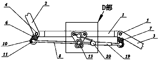
[0018] Embodiment 1: as figure 1 The seat folding degree locking device shown includes a seat board, a backrest 2, a leg rest 3, and adjustment components. The rear end of the seat board 1 is hinged with the lower end of the backrest 2 through the rear fixed shaft 4 , and the leg holder 3 is hinged with the front fixed shaft 5 at the front side of the seat board 1 . Moreover, the upper side of the leg rest 3 is provided with a leg rest driving rod 7 that exceeds the front fixed shaft 5 and is bent downwards and extended to. And the lower side of the backrest 2 is provided with a backrest drive rod 6 that exceeds the rear fixed axis 4 and bends downwards to extend.

[0019] The ends of the backrest driving rod 6 and the leg rest driving rod 7 are respectively hinged in the axle sleeves at the two ends of the linkage rod 8 through inner shafts.

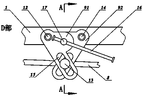
[0020] Adjusting parts for controlling the swivel degree of backrest 2 and leg rest 3, see figure 2 As shown, a sizing shaft 13 is...

Embodiment 2

[0026] Embodiment 2: On the basis of Embodiment 1, the linkage rod 8 is divided into two independent sub-rods, wherein the end of one sub-rod is fixed with a length adjustment sleeve 19, and the other sub-rod penetrates the length adjustment sleeve In the pipe 19, a locking screw 20 is arranged at the port of the length adjusting sleeve 19. The purpose of controlling the length of the linkage rod 8 can be achieved by controlling the degree of expansion and contraction of the linkage rod 8 in the length adjustment sleeve 19 . Therefore, when performing synchronous control of the backrest 2 and the leg rest 3, the two can be kept moving synchronously at different angles.


PUM


Abstract

The invention discloses a seat folding degree linkage locking device. A seat plate is hinged to a backrest and leg supports; the backrest and extending parts of the leg supports are separately hingedto two sections of a linkage rod; a typing shaft arranged in the middle of the linkage rod is positioned in automatic adjusting flat holes of two swing plates; a locking pin is mounted on a supportingframe through threads; and a pressure disc on the inner side of locking pin is used for squeezing the left swing plate and the right swing plate at the same time. The device can lock a folding seat after the seat swings arbitrarily, and is simple and convenient to operate. The device can simplify the structure of the current folding seat, can obviously reduce the cost of the folding seat, and canstill achieve the purposes of the adjustment in any folding positions and locking at any moment.

Description

Technical field: [0001] The invention relates to the improvement technology of a folding seat adjustment component, in particular to a seat folding degree interlocking locking device. Background technique: [0002] At present, the existing folding seat can only hinge the backrest and the seat board together, and control the folding degree of the folding seat by controlling the swinging range and locking relationship between the two. However, if the backrest and the leg rest are linked to move, then the linkage rod must have a certain swing range, and cannot always be horizontal or move at a certain inclination angle. Due to the swinging motion of the linkage rod, there is currently no suitable structural solution for locking the linkage rod against any swing. Invention content: [0003] The present invention aims at the problem that the backrest and the leg rest cannot be linked with the current folding seat, and the problem that the linkage process cannot be effectively ...

Claims


Application Information

Patent Timeline
Patent Type & Authority Applications(China)
IPC IPC(8): A47C1/032A47C4/28A47C7/00
CPCA47C1/03238A47C4/28A47C7/00
Inventor 张瑞佳
Owner 郑州海擎电子技术有限公司
Learn More