Optical projection apparatus and control method thereof

A technology of optical projection and control method, applied in the fields of optoelectronics and optics, which can solve problems such as improper handling and human eye safety problems

Inactive Publication Date: 2018-06-05
SHENZHEN ORBBEC CO LTD
View PDF15 Cites 4 Cited by
  • Summary
  • Abstract
  • Description
  • Claims
  • Application Information

AI Technical Summary

Problems solved by technology

The energy of the zero-order diffracted beam is often several orders of magnitude higher than that of the high-order diffracted beam, and if it is not handled properly, it is very likely to induce human eye safety problems

Method used


Image

  • Optical projection apparatus and control method thereof
  • Optical projection apparatus and control method thereof
  • Optical projection apparatus and control method thereof

Examples


Embodiment Construction

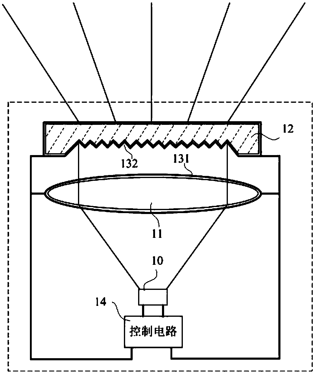
[0017] The present invention will be described in detail below through specific embodiments in conjunction with the accompanying drawings, so as to better understand the present invention, but the following embodiments do not limit the scope of the present invention. In addition, it should be noted that the diagrams provided in the following embodiments are only schematically illustrating the basic concept of the present invention, and only the components related to the present invention are shown in the drawings rather than the number of components, Shape and size drawing, the shape, quantity and proportion of each component can be changed arbitrarily during actual implementation, and the layout of the components may also be more complicated.

[0018] It should be understood that the orientation or positional relationship indicated by the terms "upper", "lower", "front", "rear", "inner", "outer", "left", "right" etc. The orientation or positional relationship is only for the ...


PUM


Abstract

The present invention discloses an optical projection apparatus comprising a light source emitting a light beam; a lens receiving and converging the light beam emitted by the light source and projecting a parallel light beam; a diffractive optical element receiving and splitting the parallel light beam passing through the lens and projecting a patterned light beam; a transparent conductive film attached to the surface of the lens and / or the diffractive optical element and having a resistive property; a control circuit module electrically connected to the transparent conductive film and the light source and used for obtaining the resistance of the transparent conductive film to determine the integrity of the lens and / or the diffractive optical element, and selecting a preset modulation function to adjust the light emitting power of the light source so as to control the light emitting power of the light source according to the state of the optical element.

Description

technical field [0001] The invention relates to the fields of optics and optoelectronics, in particular to an optical projection device and a control method thereof. Background technique [0002] Optical projection devices are widely used in 3D scanning of objects, 3D spatial reconstruction, human-computer interaction and other fields. The optical projection device marks the spatial information of the target object by projecting coded or structured special light patterns, and provides preparations for the information collection and three-dimensional reconstruction of the later image acquisition device. [0003] An optical projection device for projecting a structured light pattern generally includes a light source and a diffractive optical element (DOE). Among them, when the beam emitted by the light source has a large divergence angle, it is often necessary to use a collimator lens to converge and collimate the beam to project a parallel beam outward; among them, the DOE i...

Claims


Application Information

Patent Timeline
Patent Type & Authority Applications(China)
IPC IPC(8): G03B21/00G03B21/14G03B21/20
CPCG03B21/00G03B21/14G03B21/20
Inventor 王献冠张丁军邓想全
Owner SHENZHEN ORBBEC CO LTD
Why Eureka
Try Eureka