Swathing band type coupler

A type of coupling and wrapping technology, applied in the direction of couplings, elastic couplings, mechanical equipment, etc., can solve the problems of difficult to connect special-shaped shaft parts, limited application scope, etc.

Pending Publication Date: 2018-06-05
ZHENGZHOU TECHN COLLEGE
View PDF0 Cites 0 Cited by
  • Summary
  • Abstract
  • Description
  • Claims
  • Application Information

AI Technical Summary

Problems solved by technology

[0002] Existing couplings generally can only connect rotary shaft parts, and often have high requirements for the manufa

Method used


Image

  • Swathing band type coupler
  • Swathing band type coupler
  • Swathing band type coupler

Examples


Embodiment 1

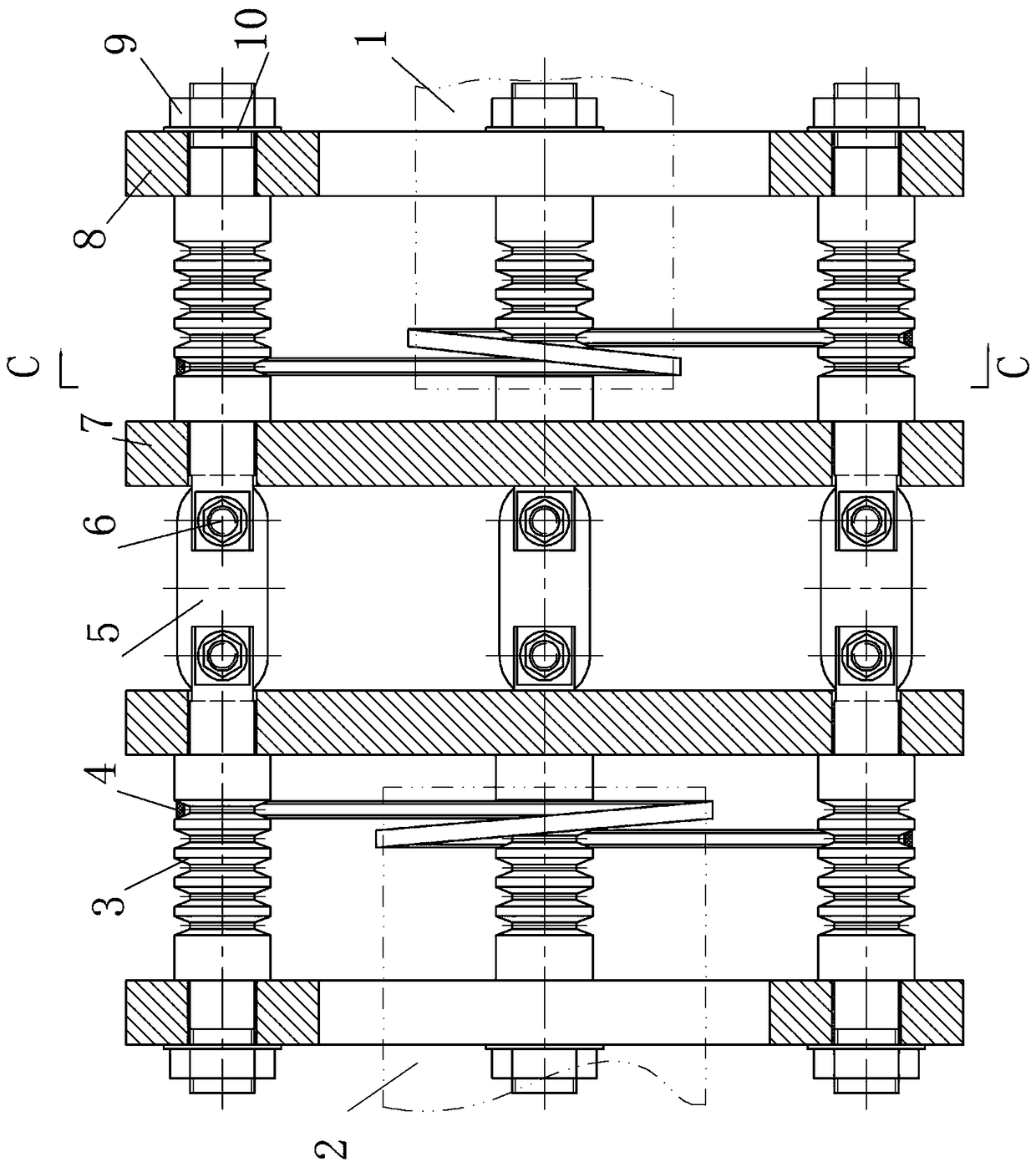
[0027] Embodiment one: see Figure 1-10 , a tape-winding coupling in the figure, including a coupling plate, a support plate, a coupling rod, a tape-winding rod, and a belt, is characterized by:

[0028] The middle part of the tape winding rod is a belt groove, and its two ends are respectively close to the connecting plate and the support plate, wherein, the end of the stepped shaft near the end of the support plate is threaded, one side of the support plate is close to the stepped surface of the stepped shaft, and the other side is connected to the tape. The rod is fastened by nuts and gaskets;

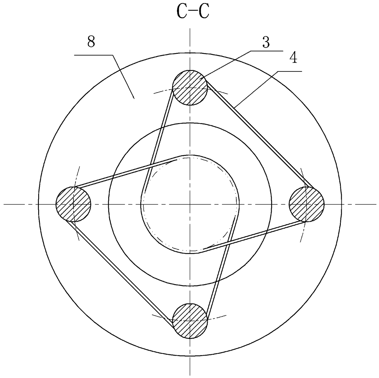
[0029] The connecting plate is disc-shaped, and there are four or eight through holes along the circumferential direction at its edge to allow the tape-wrapping rod to pass through;

[0030] The support plate is in the shape of a ring, and the middle part is used for passing the driving shaft or the driven shaft. There are four or eight through holes along the circumferential direc...


PUM


Abstract

The invention discloses a swathing band type coupler. A main body of the swathing band type coupler is composed of a connection disk, a supporting disk, a connection rod, a swathing band rod and a belt, wherein the belt is wound between the swathing band rod and a driving shaft and between the swathing band rod and a driven shaft, the driving can drive the coupler to rotate through the belt, and the coupler can drive the driven shaft to rotate through the belt between the driven shaft and the swathing band rod. The device has the advantages of simple structure, safety, reliability, conveniencein use, convenience in manufacturing, disassembling, assembling, carrying, adjusting and maintaining and adaptivity to deviation caused by bearing and temperature change in manufacturing, installing,abrasion and work of the relative position of a shaft to be coupled; thus, the work situation is effectively improved, additional load is reduced, device vibration is prevented, and service life is prolonged.

Description

technical field [0001] The invention relates to the field of shaft couplings, in particular to a tape-winding type shaft coupling. Background technique [0002] Existing couplings generally can only connect rotary shaft parts, and often have high requirements for the manufacture and installation of the two connected shafts. Irregular special-shaped shaft parts, so the scope of application is limited. Contents of the invention [0003] In order to solve the above problems, the present invention proposes a belt coupling. [0004] Technical scheme of the present invention is: [0005] A tape-winding coupling, including a coupling plate, a support plate, a coupling rod, a tape-winding rod, and a belt, is characterized in that: [0006] The middle part of the tape winding rod is a belt groove, and its two ends are respectively close to the connecting plate and the support plate, wherein, the end of the stepped shaft near the end of the support plate is threaded, one side of ...

Claims


Application Information

Patent Timeline
IPC IPC(8): F16D3/52
CPCF16D3/52
Inventor 王均杰刘燕明田新景宋宪华楚钊
Owner ZHENGZHOU TECHN COLLEGE
Why Eureka
Try Eureka