
New energy automobile battery protection device

A battery protection device and new energy vehicle technology, applied in the direction of secondary batteries, battery pack components, circuits, etc., can solve problems such as battery overheating, no shock absorbing device installed, battery damage, etc., to prolong service life and stability Good results

Inactive Publication Date: 2018-06-01
DONGGUAN XIANGFEI INTELLIGENT EQUIP TECH CO LTD
View PDF0 Cites 1 Cited by
  • Summary
  • Abstract
  • Description
  • Claims
  • Application Information

AI Technical Summary

Problems solved by technology

[0004] The purpose of the present invention is to provide a new energy vehicle battery protection device to solve the problem that the existing new energy vehicle battery protection device proposed in the background technology is usually closely connected between the battery and the battery. Such a connection mode makes the battery and the battery It is easy to exchange heat between them, which will cause the battery to overheat and affect the service life of the battery. Without a shock absorber, the battery will be loosened by the vibration of the internal motor of the car during the operation of the car, which will easily damage the battery. Battery protection There is no heat dissipation device inside the device, and only the heat dissipation holes are used for natural heat dissipation. This heat dissipation method prevents the heat between the batteries from being effectively removed, and the heat dissipation effect is poor. There is no fixing device between the battery and the protection device. Cannot be placed according to a certain amount of battery, which affects the stability of the battery after placement, and the shape of the placement slot cannot be adjusted according to the length of the battery, making it a problem that the range of use is small

Method used


Image

  • New energy automobile battery protection device
  • New energy automobile battery protection device
  • New energy automobile battery protection device

Examples


Embodiment Construction

[0027] The technical solutions in the embodiments of the present invention will be clearly and completely described below in conjunction with the accompanying drawings in the embodiments of the present invention. Obviously, the described embodiments are only some of the embodiments of the present invention, not all of them. Based on The embodiments of the present invention and all other embodiments obtained by persons of ordinary skill in the art without making creative efforts belong to the protection scope of the present invention.

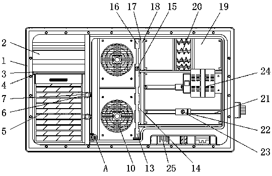
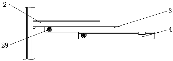
[0028] see Figure 1-5, the present invention provides a technical solution: a battery protection device for new energy vehicles, including a protection device body 1, a fixed slide plate 2, a first sliding cover 3, a second sliding cover 4, a battery storage area 5, a power collection tank 6, Power collector 7, power transmission block 8, transmission connection groove 9, heat dissipation fan 10, battery separator 11, battery fixing groove 12, ...


PUM


Abstract

The invention relates to a new energy automobile battery protection device. The new energy automobile battery protection device comprises a protection device main body, a power transmission block anda shock absorbing zone. The back surface of a first sliding cover is connected to a second sliding cover. The back of the second sliding cover is provided with a battery storage zone. A heat dissipation fan is installed in the right side of the power transmission block. A battery partition plate is fixed on the front end surface of the heat dissipation fan. A first rotation shaft is installed on the upper end of an isolation rod. The outer side of the first rotation shaft is connected to an adjustment rod. The shock absorbing zone is installed in the right side of a battery fixing frame. The heat dissipation fan can dissipate heat of the bottom of a battery so that heat between the batteries is fully dissipated. The first and second sliding covers can prevent the battery from excessively contacting with air. The adjustment rod and the isolation rod are rotated so that the battery arrangement position is changed. The battery fixing frame is separated from the protection device main bodyso that a storage space between the batteries is easy to adjust.

Description

technical field [0001] The invention relates to the technical field of new energy vehicle batteries, in particular to a new energy vehicle battery protection device. Background technique [0002] The new energy vehicle battery is the power battery, that is, the power supply that provides the power source for the tool. It mostly refers to the battery that provides power for electric vehicles, electric trains, electric bicycles, and golf carts. It is mainly different from the starter battery used for starting the car engine. Valve-port sealed lead-acid batteries, open tubular lead-acid batteries and lithium iron phosphate batteries are mostly used, which are safe to use. Lithium iron phosphate completely solves the potential safety hazards of lithium cobaltate and lithium manganate. Lithium cobaltate and manganese Lithium acid will explode under strong collision and pose a threat to the life safety of consumers, while lithium iron phosphate will not explode even in the worst t...

Claims


Application Information

Patent Timeline
IPC IPC(8): H01M2/10H01M10/613H01M10/625H01M10/6563H01M50/249
CPCH01M10/613H01M10/625H01M10/6563H01M50/20Y02E60/10
Inventor 邓凯谢海燕
Owner DONGGUAN XIANGFEI INTELLIGENT EQUIP TECH CO LTD
Learn More