Sliding frictional force generation mechanism and manufacture method thereof, mold buffer device and metal die

A technology of sliding friction force and buffer device, applied in manufacturing tools, presses, etc., can solve the problem of not using friction force, etc., and achieve the effect of high oil film maintenance, improved cooling efficiency, and high durability

Active Publication Date: 2018-06-01
AIDA ENG LTD
View PDF10 Cites 3 Cited by
  • Summary
  • Abstract
  • Description
  • Claims
  • Application Information

AI Technical Summary

Problems solved by technology

More precisely, the technology is about the technology of the sealing structure, and does not point out the use of friction

Method used


Image

  • Sliding frictional force generation mechanism and manufacture method thereof, mold buffer device and metal die
  • Sliding frictional force generation mechanism and manufacture method thereof, mold buffer device and metal die
  • Sliding frictional force generation mechanism and manufacture method thereof, mold buffer device and metal die

Examples


Embodiment Construction

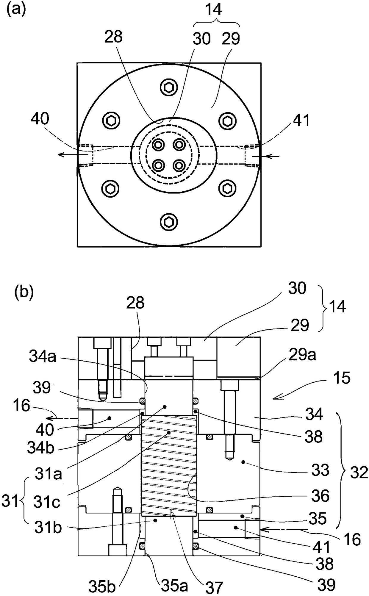
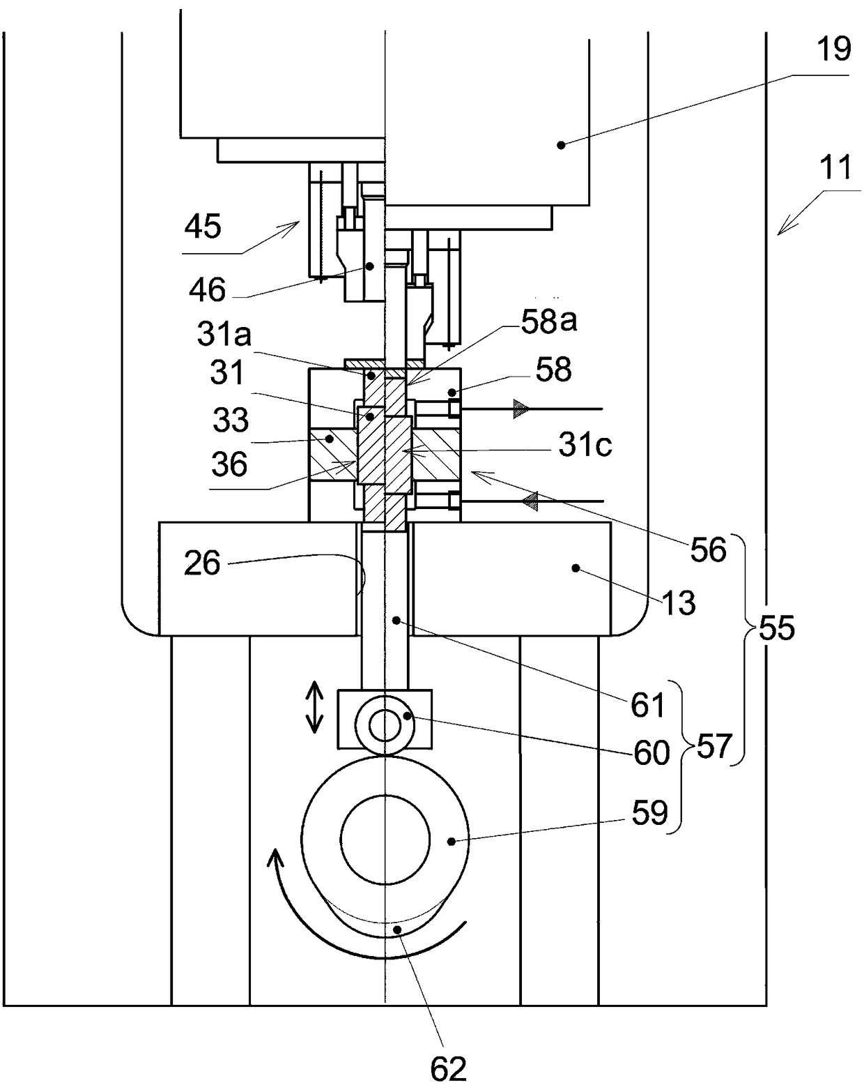
[0053] figure 1 , figure 2 a and figure 2 The mold buffer device 10 shown in b is composed of a normal-pressure air buffer device 12 installed on the press machine 11 and arranged under the backing plate 13, and combined with the lower part of the lower mold 14 arranged on the backing plate 13. The friction die buffer 15 constitutes. Reference numeral 16 is a supply system for supplying and circulating lubricating oil which also serves as cooling oil to the friction die cushion 15 . figure 1 The left side of is the state that the slider of press machine 11 is rising, and the right side is the state of falling. exist image 3 , Figure 4 It is the same in a. The press machine 11 is composed of a frame 18, the above-mentioned backing plate 13, a slider 19 that moves up and down, and a known slider driving mechanism (not shown) that drives the slider up and down.

[0054] The air cushion device 12 includes a multi-stage bellows 20, air (pressurized air) filled inside, ...


PUM

PropertyMeasurementUnit
surface roughnessaaaaaaaaaa
heightaaaaaaaaaa

Abstract

The invention provides a sliding frictional force generation mechanism and a manufacture method thereof, a mold buffer device and a metal die. The sliding frictional force generation mechanism can stably exert greater load and is highly endurable and applied to mold buffer of a pressure machinery. A friction mold buffer (15) comprises a shaft sleeve (33) with a friction hole (36), a friction pin (31) embedded to freely slide in an axial direction in the friction hole (36) and a supply system (16) used for supplying lubricating oil as a cooling medium between the friction hole (36) and the friction pin (31). The friction hole (36) and the friction pin (31) are embedded in the state of interference fit. A mold buffer device (10) is in series connection with the friction mold buffer (15) andan air buffer device (12).

Description

technical field [0001] The present invention relates to a fitting-based sliding friction generating mechanism and a die shock absorber of a press machine using the sliding friction generating mechanism. Background technique [0002] In the fitting of the shaft and the hole, there are known "clearance fit" for obtaining a slidable fit, "interference fit" for fixing the shaft to the hole, and "intermediate fit" for intermediate fitting between the two. Cooperate". These fits are selected by specifying dimensional tolerances for the bore and shaft diameters. These fits are known, for example, from Non-Patent Document 1 and others. According to "4.10.2" of Non-Patent Document 1, "interference fit: a fitting that always produces an interference margin when assembling a hole and a shaft". Such an interference fit is used when there is substantially no movement and disassembly after assembly. Pressing, heat fitting, and cold embedding are required in assembly. [0003] On the o...

Claims


Application Information

Patent Timeline
Patent Type & Authority Applications(China)
IPC IPC(8): B30B15/02B30B15/00
CPCB30B15/00B30B15/0088B30B15/02B21D24/06B30B15/026B30B15/281B30B15/34B21D24/02
Inventor 伊藤隆夫
Owner AIDA ENG LTD
Why Eureka
Try Eureka