Mobile extrusion rod structure
A rod structure, mobile technology, applied in the field of machinery, can solve the problems of long body length of the extruder, high cost of mechanical manufacturing materials, long reactive production time, etc. Simple and reasonable structure
- Summary
- Abstract
- Description
- Claims
- Application Information
AI Technical Summary
Problems solved by technology
Method used
Image

Examples
specific Embodiment approach 1
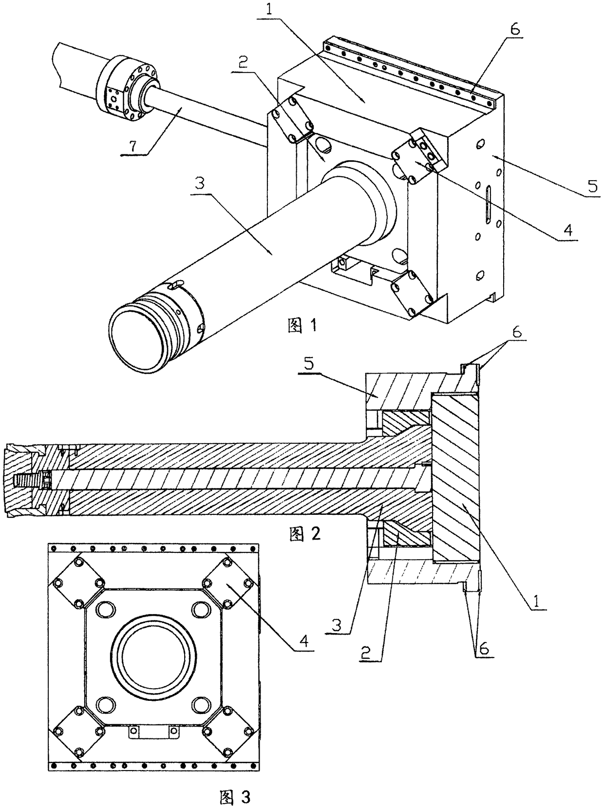
[0045] The present invention will be described in detail below in conjunction with the accompanying drawings. As attached to the manual figure 1 , 2 , 3, 4, 5, 6, 7, 8, 9, 10:
[0046] A mobile extruding rod structure, consisting of a pad 1, a gland 2, an extruding rod 3, an oil cylinder 4, a seat 5, a slide plate 6, and a hydraulic cylinder 7 to form a mobile extruding rod structure 20;
[0047] The movable extruded rod structure, the flanges on the upper and lower sides of the seat 5 are all connected with the hydraulic rod end of the hydraulic cylinder 7, the left side of the slide plate 6, the seat 5, and the four corners of the front of the seat 5 are all connected with the oil cylinder 4, the seat The center hole of 5 is fixedly connected with pad 1, pad 1 and gland 2, and the trapezoidal seat with slope of extruding rod 3 is placed in the trapezoidal center hole with slope of gland 2, and the seat of trapezoidal seat with slope of extruding rod 3 The bottom is conne...
specific Embodiment approach 2
[0057] Implementation is carried out on the basis of specific implementation mode 1 implementation. Just: specifically only implement the mobile extruding rod structure among the present invention. The mobile extrusion rod structure in the present invention will be described in detail below in conjunction with the accompanying drawings. As attached to the manual figure 1 , 2 , as shown in 3:
[0058] A mobile extruding rod structure, consisting of a pad 1, a gland 2, an extruding rod 3, an oil cylinder 4, a seat 5, a slide plate 6, and a hydraulic cylinder 7 to form a mobile extruding rod structure 20;
[0059] The movable extruded rod structure, the flanges on the upper and lower sides of the seat 5 are all connected with the hydraulic rod end of the hydraulic cylinder 7, the left side of the slide plate 6, the seat 5, and the four corners of the front of the seat 5 are all connected with the oil cylinder 4, the seat The center hole of 5 is fixedly connected with pad 1, ...
specific Embodiment approach 3
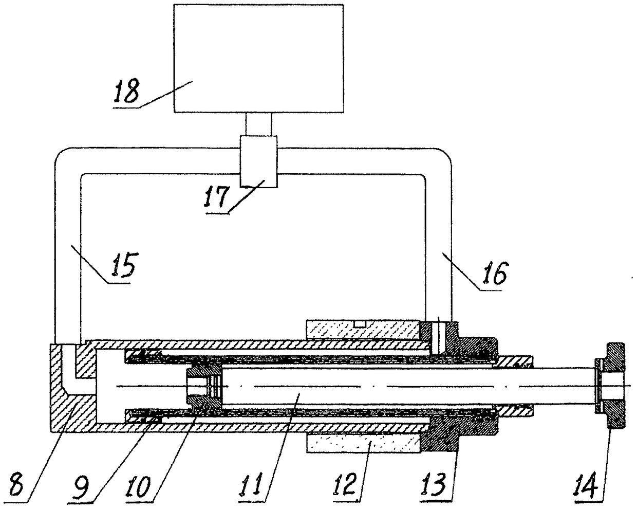
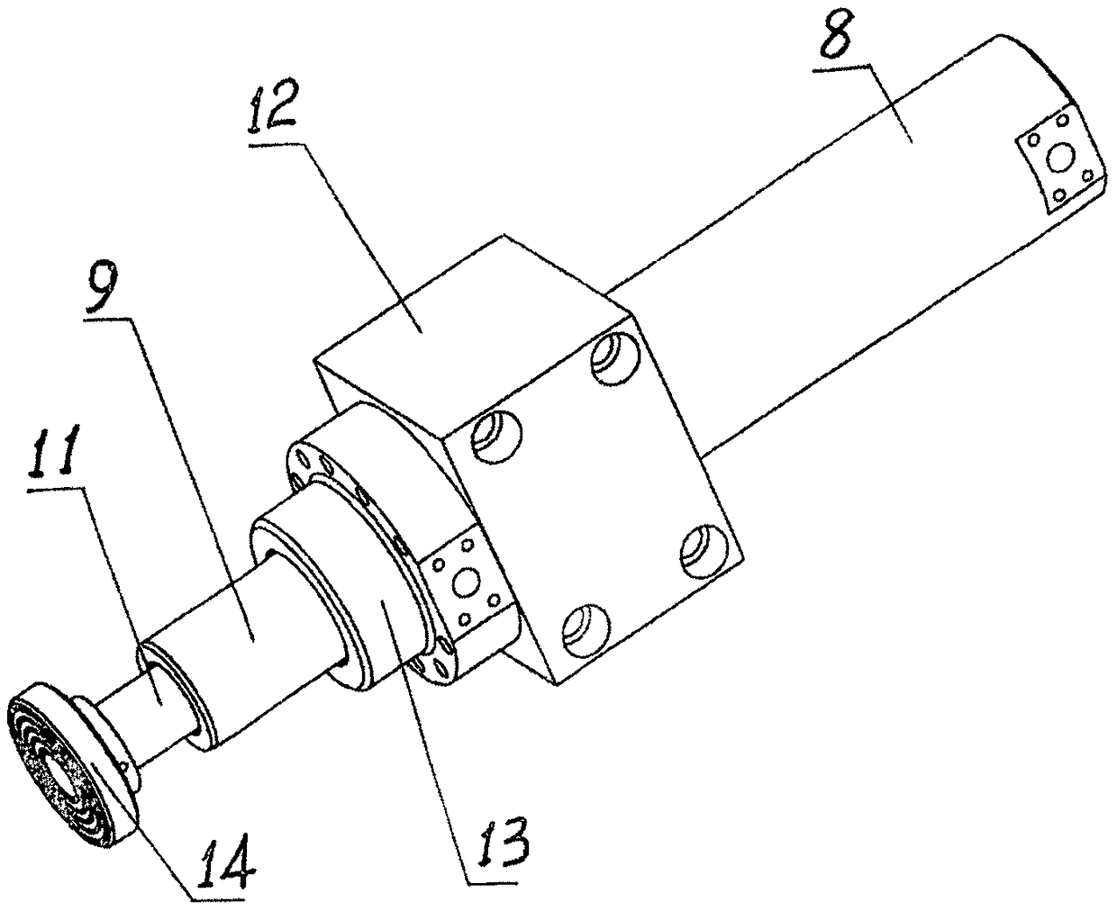
[0063] Implementation is carried out on the basis of specific implementation mode 1 implementation. Just: specifically only implement the multistage rod pusher among the present invention. The multi-stage rod pusher in the present invention will be described in detail below in conjunction with the accompanying drawings of the description. As attached to the manual Figure 4 , 5 Shown:
[0064] A multi-stage rod pusher, consisting of an outer cylinder 8, an inner cylinder 9, a piston 10, a piston rod 11, a mounting seat 12, a guide head 13, a push block 14, a left pipe 15, a right pipe 16, an oil passage 17, Fuel tank 18 constitutes multistage rod pusher 19;
[0065] Described multi-stage rod pusher, the inner wall of its outer cylinder 8 and the slide block on the outer wall of the left rear end of the inner cylinder 9, the outer wall of the inner cylinder 9 and the central hole of the guide head 13 are all slidingly connected left and right, and its outer The right end o...
PUM
 Abstract
Description
Claims
Application Information
 - R&D
- Intellectual Property
- Life Sciences
- Materials
- Tech Scout
- Unparalleled Data Quality
- Higher Quality Content
- 60% Fewer Hallucinations
Browse by: Latest US Patents, China's latest patents, Technical Efficacy Thesaurus, Application Domain, Technology Topic, Popular Technical Reports.
© 2025 PatSnap. All rights reserved.Legal|Privacy policy|Modern Slavery Act Transparency Statement|Sitemap|About US| Contact US: help@patsnap.com