
Combined air filter and vehicle

An air filter and filter element technology, which is applied in the automotive field, can solve problems such as hydrocarbon leakage and difficulty in arranging noise reduction function components, and achieve the effects of good durability, solving hydrocarbon leakage, and simple structure

Pending Publication Date: 2018-05-29
宜润邦科技(河北)有限公司
View PDF4 Cites 1 Cited by
  • Summary
  • Abstract
  • Description
  • Claims
  • Application Information

AI Technical Summary

Problems solved by technology

[0006] Adopting the above-mentioned technical solution, it solves the problem of difficult layout of noise-reduction function components caused by the limited space in the engine compartment, and also solves the problem of hydrocarbon leakage under the National VI emission requirements. The process cost is low, the process is good, the durability is good, the advantages of energy saving and environmental protection, etc.

Method used


Image

  • Combined air filter and vehicle
  • Combined air filter and vehicle

Examples


Embodiment Construction

[0017] The specific implementation manners according to the present invention will be described below in conjunction with the accompanying drawings.

[0018] In the following description, many specific details are set forth in order to fully understand the present invention, but the present invention can also be implemented in other ways different from those described here, therefore, the present invention is not limited to the specific embodiments disclosed below limit.

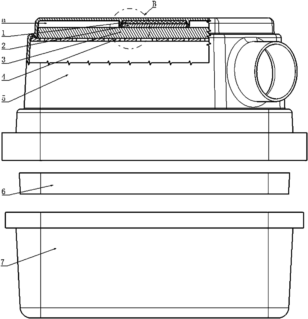
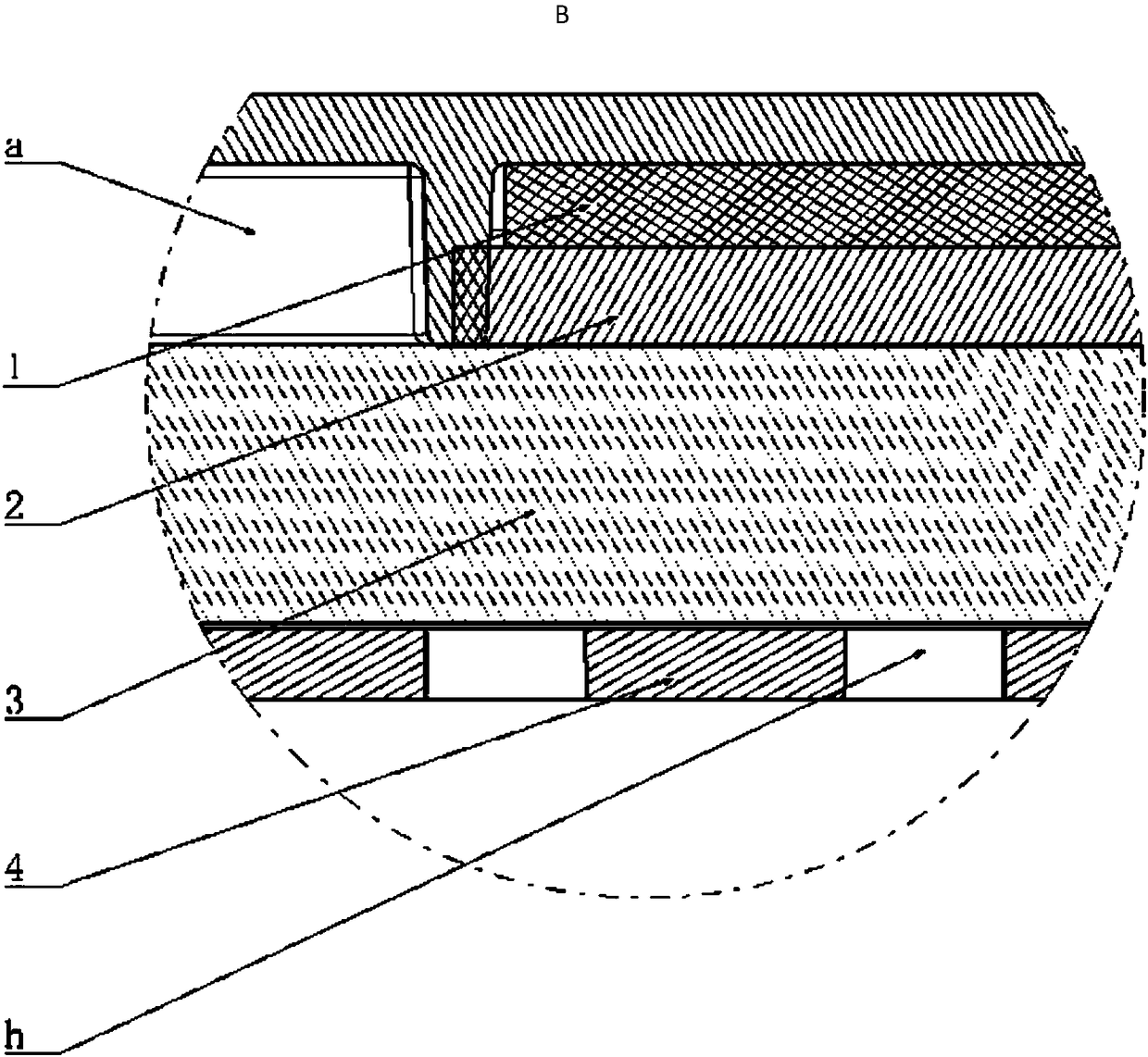
[0019] figure 1 A partially cutaway schematic diagram showing an embodiment of the composite air filter according to the present invention, figure 2 show figure 1 An enlarged schematic view at B of the illustrated example.

[0020] As shown in the figure, in order to solve the above technical problems, the present invention provides a composite air filter.

[0021] The composite air filter provided by the present invention includes: an upper casing 5, a lower casing 7, a filter element 6, a porous plate...


PUM


Abstract

The invention provides a combined air filter. The combined air filter comprises an upper shell, a lower shell, a filter element, a multi-hole plate and an adsorption layer. The upper shell and the lower shell are fixedly connected to form an airtight cavity, and the filter element is arranged in the airtight cavity. The multi-hole plate is arranged on the top of the upper shell so that a noise reduction cavity can be formed between the multi-hole plate and the top wall of the upper shell. The adsorption layer is arranged in the noise reduction cavity. By adopting the technical scheme, the problem that the space inside an engine cabin is limited, and consequently the noise reduction functional components are difficult to distribute is well solved, meanwhile, the hydrocarbon leakage problemunder the emission requirements in CN6 is also solved, two purposes are achieved at one stroke, and meanwhile, the combined air filter has the beneficial effects of being simple in structure, relatively low in process cost, good in manufacturability and durability, capable of saving energy, environment-friendly and the like. The invention further discloses a vehicle provided with the combined airfilter.

Description

technical field [0001] The invention relates to the field of automobiles, in particular to a composite air filter. The present invention also relates to a vehicle including the composite air filter. Background technique [0002] At present, the air filter has a structure designed to reduce noise, and another part is fixed by welding or other processes on the shell. This part has a porous structure designed for special acoustic purposes, making it It forms a cavity with the housing, and allows the airflow flowing through the air filter to enter and exit the cavity freely, such as the patent No. 201621307321.8 titled "Air Filter, Engine Intake System and Vehicle" , The air filter includes an air filter housing, an air filter inlet duct, an air filter outlet duct, a filter element and a hydrocarbon adsorption device. At present, the air filter also has a structural design of a hydrocarbon adsorption device. The hydrocarbon adsorption device is mostly paper or non-woven fabric...

Claims


Application Information

Patent Timeline
Patent Type & Authority Applications(China)
IPC IPC(8): F02M35/024F02M35/14
CPCF02M35/0216F02M35/0218F02M35/024F02M35/1272F02M35/14
Inventor 宋金环姚连泉薄源李丽萍韩海安
Owner 宜润邦科技(河北)有限公司
Learn More