
Heating device for physical test

A heating device and physical test technology, applied to heating or cooling equipment, laboratory appliances, supporting appliances, etc., can solve the problems of low heating efficiency, inconvenient adjustment of the heating position of the alcohol lamp, etc., and achieve protection stability and test efficiency Improvement, placement stability effect

Inactive Publication Date: 2018-05-29
成都酷爱睿工业产品设计有限公司
View PDF0 Cites 4 Cited by
  • Summary
  • Abstract
  • Description
  • Claims
  • Application Information

AI Technical Summary

Problems solved by technology

[0002] In physics class, it is often necessary to do various heating experiments. When performing heating experiments, it is usually necessary to use a heating frame, which can support the alcohol lamp and the object to be heated, but the heating frame in the prior art is a simple The iron frame is inconvenient to adjust the heating position of the alcohol lamp, so the outer flame of the alcohol lamp cannot be used for heating, and the heating efficiency is relatively low. Therefore, we propose a heating device for physical experiments

Method used


Image

  • Heating device for physical test

Examples


Embodiment Construction

[0013] The technical solutions in the embodiments of the present invention will be clearly and completely described below in conjunction with the accompanying drawings in the embodiments of the present invention. Obviously, the described embodiments are only a part of the embodiments of the present invention, rather than all the embodiments.

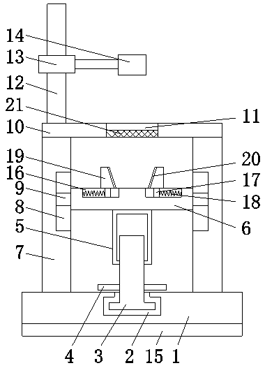
[0014] Reference figure 1 , A heating device for physical testing, including a base 1. A suction cup 15 is provided at the lower end of the base 1. The base 1 needs to be placed on a horizontal tabletop. The suction cup 15 can ensure the stability of the base 1 when placed, making the test process safer. reliable.

[0015] A T-shaped groove 2 is opened at the center of the upper side of the base 1, a T-shaped threaded rod 3 is rotatably arranged in the T-shaped groove 2, a rotating button 4 is sleeved on the outer side of the T-shaped threaded rod 3, and the upper end of the T-shaped threaded rod 3 is sleeved on the outer side Threaded pipe ...


PUM


Abstract

The invention relates to the technical field of heating devices, in particular to a heating device for a physical test. The heating device comprises a base, wherein a T-shaped groove is formed in thecenter of the upper side of the base; a T-shaped threaded rod is rotationally arranged in the T-shaped groove; a rotary switch is arranged on the outer side of the T-shaped threaded rod in a sleevingmanner; a threaded pipe is arranged on the outer side of the upper end of the T-shaped threaded rod in the sleeving manner; a putting board is fixedly supported at the upper side of the threaded pipe;limiting plates are fixed at two ends of the upper side of the base; sliding rails are respectively arranged at certain sides, which are opposite to each other, of the limiting plates; sliding blocksare arranged in the sliding rails in a sliding manner; in addition, the other sides of two sliding blocks are respectively fixed at two sides of the putting boards; a limiting mechanism is arranged at the upper side of the putting board; a supporting plate is fixed at the upper ends of the two limiting plates; a heating hole is formed in the center of the upper side of the supporting plate in a penetrating manner; a threaded rod is fixed at one end of the upper side of the supporting plate; a threaded sleeve is arranged on the threaded rod in a sleeving manner. The heating device disclosed bythe invention has the advantages that the position of an alcohol lamp can be quickly adjusted, a heating object can be able to contact with the outer flame of the alcohol lamp and the heating efficiency is improved.

Description

Technical field [0001] The invention relates to the technical field of heating devices, in particular to a heating device for physical tests. Background technique [0002] In physics classes, it is often necessary to do various heating tests. In the heating test, a heating rack is usually used. The alcohol lamp and the object to be heated can be supported by the heating rack. However, the heating rack in the prior art is a simple The iron frame body is inconvenient to adjust the heating position of the alcohol lamp, so the outer flame of the alcohol lamp cannot be used for heating, and the heating efficiency is relatively low. For this reason, we propose a heating device for physical experiments. Summary of the invention [0003] The purpose of the present invention is to solve the shortcomings in the prior art, and propose a heating device for physical testing. [0004] In order to achieve the above objectives, the present invention adopts the following technical solutions: [0005...

Claims


Application Information

Patent Timeline
Patent Type & Authority Applications(China)
IPC IPC(8): B01L7/00B01L9/00
CPCB01L7/00B01L9/00
Inventor 代羿
Owner 成都酷爱睿工业产品设计有限公司
Learn More