Tool for hot riveting and welding sensor

A sensor and hot riveting technology, applied in the field of sensors, can solve problems such as difficult size control, poor product consistency, and affect product quality, and achieve the effects of reasonable structural design, high welding precision, and good product welding consistency

Inactive Publication Date: 2018-05-25
WUHU GRAND VISION AUTO ELECTRONICS CO LTD
View PDF3 Cites 0 Cited by
  • Summary
  • Abstract
  • Description
  • Claims
  • Application Information

AI Technical Summary

Problems solved by technology

The size of the end of the plastic column welded by the existing hot riveting welding tool is not easy to control, the welding accuracy is poor, and the product consistency is poor, which affects the product quality

Method used


Image

  • Tool for hot riveting and welding sensor

Examples


Embodiment Construction

[0016] The specific implementation manner of the present invention will be described in further detail below by describing the embodiments with reference to the accompanying drawings.

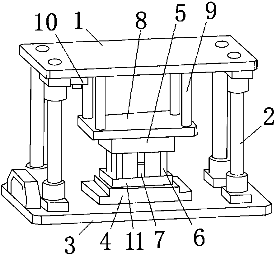
[0017] Such as figure 1 As shown, the tooling for thermal riveting welding of sensors includes a frame, an upper plate 1, a guide post 2, a bottom plate 3, a positioning plate 4, a thermal mold 5, a thermal riveting rod 6, a positioning pressure rod 7, and a thermal mold fixing plate 8. Heat insulation column 9, dust filter 10 and bottom mold 11.

[0018] The frame is a frame structure, the bottom plate is fixed on the upper part of the frame, and the hot riveting rod 6 is set under the hot mold. The hot riveting rod 6 is used to weld the end of the plastic column on the sensor. The hot riveting rod 6 is a hollow cylinder. There is an electric heating tube inside, and the upper part of the hot riveting rod is connected by a block to ensure that the height can be adjusted up and down.

[0019]...


PUM


Abstract

The invention discloses a tool for hot riveting and welding a sensor. The tool for hot riveting and welding the sensor comprises a rack, a bottom plate, a hot mold and hot riveting rods. The bottom plate is arranged on the rack; the hot riveting rods are arranged under the hot mold; and a driving cylinder for driving the hot mold to move up and down is arranged on the rack. The tool for hot riveting and welding the sensor further comprises spring limiting pillars for limiting welding sizes of the hot riveting rods, wherein the spring limiting pillars are arranged on the bottom plate; and the upper ends of the spring limiting pillars correspond to the hot mold. The tool for hot riveting and welding the sensor is reasonable in structure design; and the spring limiting pillars are arranged onthe bottom plate and are used for limiting the sizes of end parts of the hot riveting rods for welding plastic pillars on the sensor, so that the welding precision is high, and the product welding consistency is good.

Description

technical field [0001] The invention relates to the technical field of sensors, in particular to a tool for thermal riveting welding of sensors. Background technique [0002] The internal circuit board and other parts of the automotive sensor are mostly fixed by hot riveting at the end of the plastic column. The existing heat riveting welding tool is difficult to control the size of the end of the welding plastic column, the welding precision is poor, and the product consistency is poor, which affects the product quality. Contents of the invention [0003] Aiming at the deficiencies of the prior art, the technical problem to be solved by the present invention is to provide a tooling for thermal riveting welding of sensors, so as to achieve the purpose of good welding consistency. [0004] In order to solve the problems of the technologies described above, the technical solution adopted in the present invention is: [0005] The tooling for thermal riveting welding of sens...

Claims


Application Information

Patent Timeline
Patent Type & Authority Applications(China)
IPC IPC(8): B29C65/60B29C65/02B29C65/24B29C65/78
CPCB29C65/60B29C65/02B29C65/24B29C65/7805B29C66/002B29C66/0342
Inventor 孙拓夫张雪磊
Owner WUHU GRAND VISION AUTO ELECTRONICS CO LTD
Why Eureka
Try Eureka