
Permanent magnet embedded rotor iron core, motor rotor and motor

A rotor core and permanent magnet technology, applied in the direction of magnetic circuit rotating parts, magnetic circuits, electrical components, etc., can solve problems such as high distortion rate and cogging torque, small motor output torque, and large average air gap of the motor. Reach the effects of reducing back electromotive force distortion rate and cogging torque, increasing output torque, and reducing average air gap

Inactive Publication Date: 2018-05-22
GREE ELECTRIC APPLIANCES INC
View PDF4 Cites 3 Cited by
  • Summary
  • Abstract
  • Description
  • Claims
  • Application Information

AI Technical Summary

Problems solved by technology

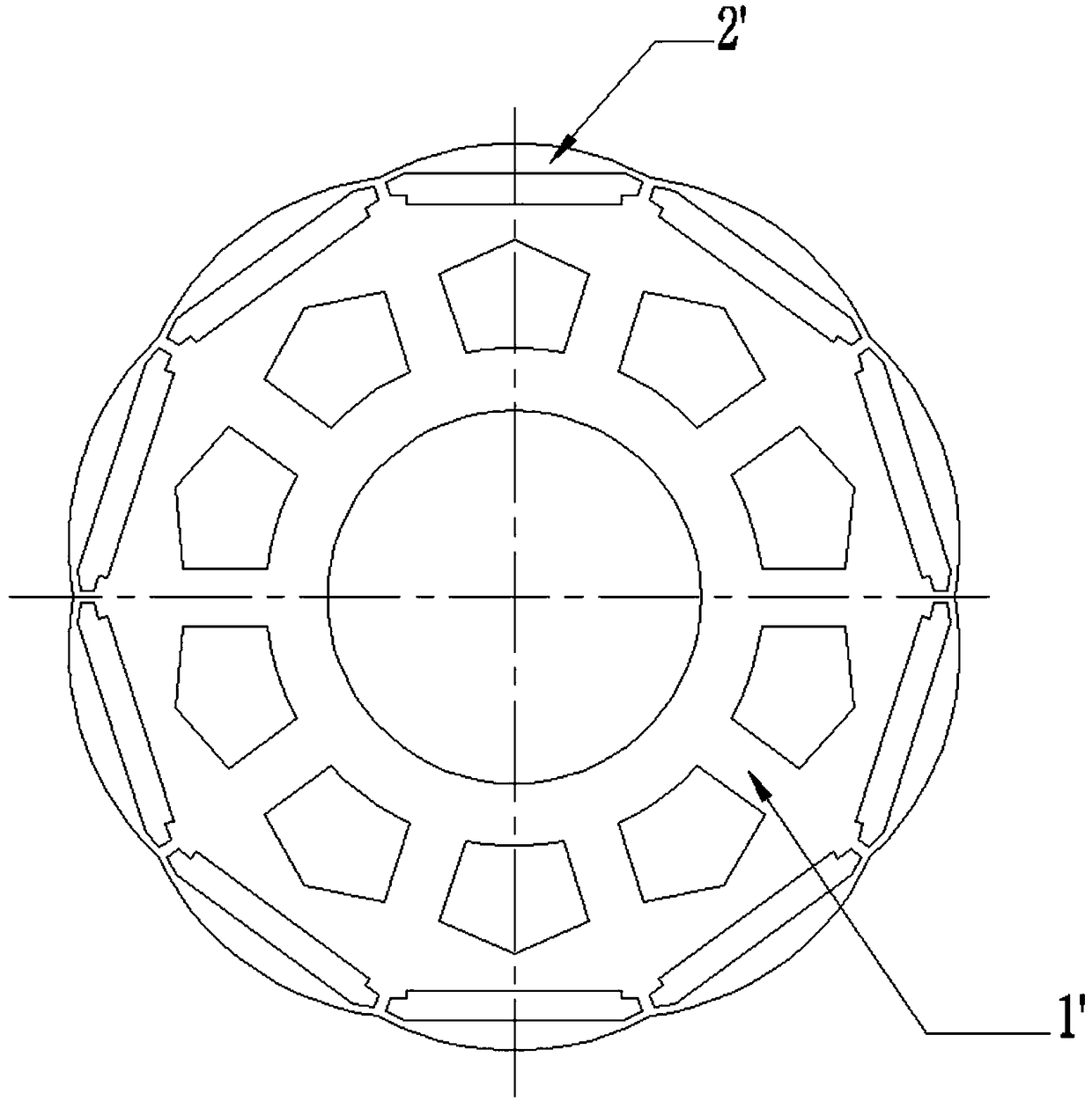
[0003] However, combined figure 1 As shown, in the existing permanent magnet embedded motor rotor structure, the outer peripheral edge of the rotor pole 2' of the rotor core 1' is usually set in a single-segment arc-shaped structure, and the center angle corresponding to the arc-shaped structure is Angle setting is unreasonable, so that the average air gap of the motor is large, resulting in small motor output torque, high back EMF distortion rate and cogging torque, low output efficiency and running accuracy

Method used


Image

  • Permanent magnet embedded rotor iron core, motor rotor and motor
  • Permanent magnet embedded rotor iron core, motor rotor and motor
  • Permanent magnet embedded rotor iron core, motor rotor and motor

Examples


Embodiment Construction

[0034] In order to further explain the technical means and functions adopted by the present invention to achieve the predetermined purpose, the specific implementation, structure, features and functions of the application according to the present invention will be described in detail below in conjunction with the accompanying drawings and preferred embodiments. In the following description, particular features, structures, or characteristics of one or more embodiments may be combined in any suitable manner.

[0035] It should be noted that, in the description of the present invention, terms such as "up", "down", "left", "right", "vertical", "horizontal", "inside", "outside" and so on indicate directions or The terms of positional relationship are based on the direction or positional relationship shown in the drawings, which are only for convenience of description, and do not indicate or imply that the device or element must have a specific orientation, be constructed and operat...


PUM


Abstract

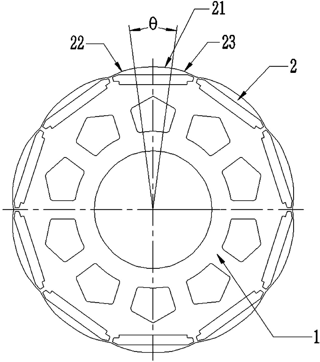
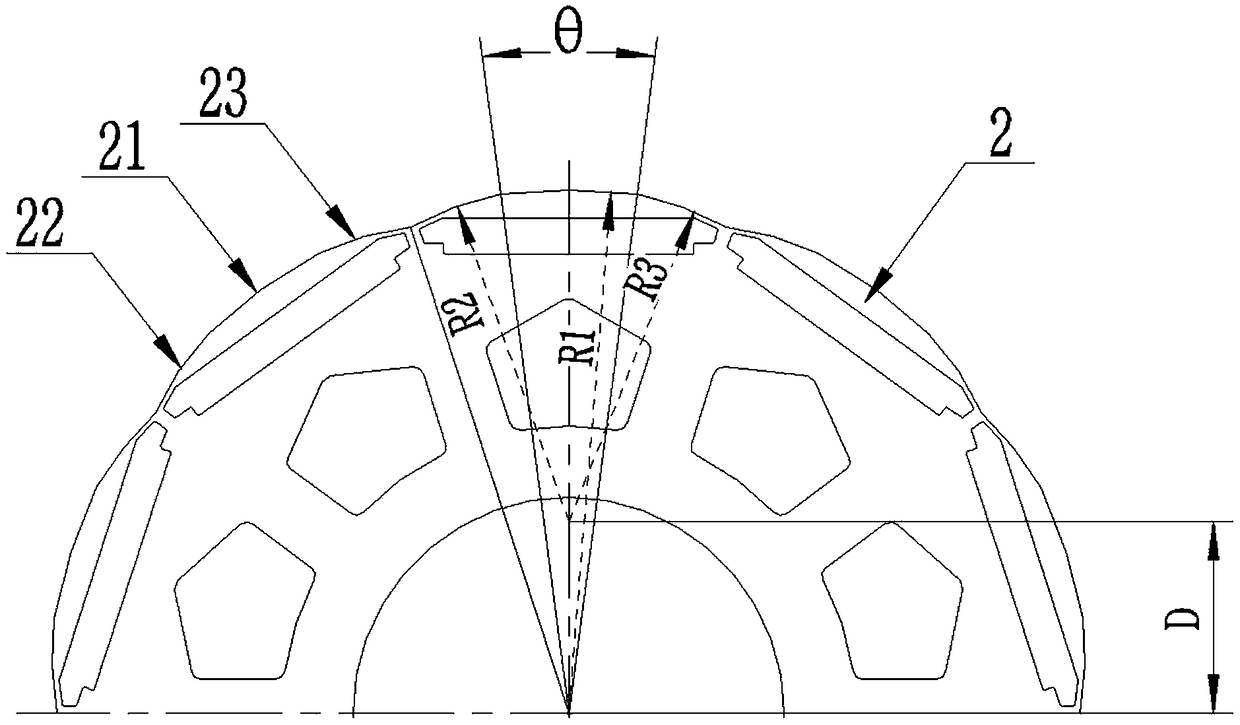
The invention relates to a permanent magnet embedded rotor iron core. The permanent magnet embedded rotor iron core includes a rotor pole. A connection line between the middle point of the outer periphery of the rotor pole and the rotation center of the rotor iron core is the central axis of the rotor pole. The outer periphery of the rotor pole includes a plurality of arc segments connected in a head-to-tail manner in sequence. One of the arc segments is arc-shaped and is the first arc segment. The first arc segment is in axial symmetry about the central axis and the angle of a central angle corresponding to the first arc segment is 12 degrees to 16 degrees. The outer periphery of the rotor pole is provided with a plurality of the arc segments connected in the head-to-tail manner in sequence, so that reduction of average air gap of a motor provided with the permanent magnet embedded rotor iron core is facilitated and the motor output torque is improved. Besides, through optimizing theposition of the first arc segment and the angle of the central angle corresponding to the first arc segment, the air gap flux distribution of the motor can be approximate to a shape of sine waves, theoutput torque of the motor can be increased further and the counter electromotive force distortion rate and the tooth socket torque of the motor can be further reduced.

Description

technical field [0001] The invention relates to the technical field of motors, in particular to a permanent magnet embedded rotor core, a motor rotor and a motor. Background technique [0002] With the rapid development of intelligent equipment such as robots, the market has higher and higher performance requirements for servo motors. Various servo motor manufacturers are striving to develop high-efficiency and high-precision servo motors. The rotor structure of the permanent magnet embedded servo motor is made of silicon steel sheet material, which has good magnetic permeability. The magnet is embedded in the rotor core 1'. Even if the rotor rotates at a high speed, the magnet will not fall off, so it has high reliability and other advantages. performance, it has gradually become more and more widely used in the servo motor industry. [0003] However, combined figure 1 As shown, in the existing permanent magnet embedded motor rotor structure, the outer peripheral edge of ...

Claims


Application Information

Patent Timeline
Patent Type & Authority Applications(China)
IPC IPC(8): H02K1/27
CPCH02K1/2766
Inventor 黄辉胡余生殷贤康陈飞龙刘娜杨文德刘吉胜张闯叶小奔
Owner GREE ELECTRIC APPLIANCES INC
Learn More