Bearing test device for applying radial alternating load based on synchronous belt drive mechanism

A synchronous belt drive, alternating load technology, applied in the direction of mechanical bearing testing, can solve problems such as single loading characteristics, inability to achieve variable load loading, difficult to carry out engine dynamic load bearing tests, etc., to achieve good results and flexible adjustment. Effect

Inactive Publication Date: 2018-05-18
SHANGHAI JIAN QIAO UNIV
View PDF0 Cites 2 Cited by
  • Summary
  • Abstract
  • Description
  • Claims
  • Application Information

AI Technical Summary

Problems solved by technology

At present, the traditional bearing test device has a single loading characteristic and cannot realize variable load loading. In real internal combustion engines, the dynamic load bearing is often under alternating loads, so it is difficult for the traditional bearing test device to carry out the test of the dynamic load bearing of the engine.

Method used


Image

  • Bearing test device for applying radial alternating load based on synchronous belt drive mechanism
  • Bearing test device for applying radial alternating load based on synchronous belt drive mechanism
  • Bearing test device for applying radial alternating load based on synchronous belt drive mechanism

Examples


Embodiment 1

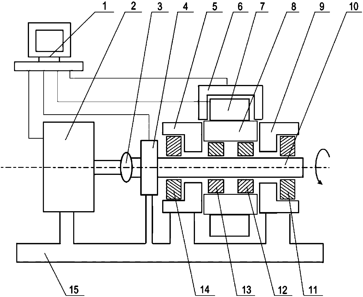
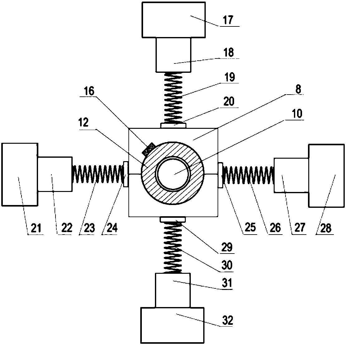
[0031] A bearing test device for applying radial alternating loads based on a synchronous belt transmission mechanism, such as figure 1 As shown, the device includes a computer 1, a drive motor 2, a coupling 3, a torque meter 4, a fixed fixture A5, an oil supply system 6, a radial alternating load loading module 7, a movable fixture 8, a fixed fixture B 9, a rotating Shaft 10, test bearing B11, test bearing B 12, test bearing A13, test bearing A14, working platform 15. Among them, such as figure 2 As shown, the radial alternating load loading module 7 includes a temperature sensor 16, a rotating motor A17, a synchronous belt transmission mechanism A18, a spring A19, a connecting device A20, a rotating motor B 21, a synchronous belt transmission mechanism B22, a spring B 23, and a connecting device B 24, connecting device C 25, spring C 26, synchronous belt drive mechanism C 27, rotating motor C28, connecting device D 29, spring D 30, synchronous belt driving mechanism D 31, ...

Embodiment 2

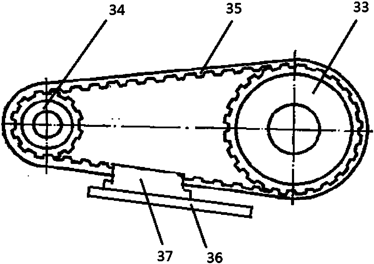
[0037] A bearing test device based on a synchronous belt drive mechanism that applies radial alternating loads, its structure is roughly the same as that of Embodiment 1, the difference is that the diameter of the driving wheel in this embodiment is the same as that of the driven wheel.


PUM


Abstract

The invention relates to a bearing test device for applying radial alternating load based on a synchronous belt drive mechanism. The bearing test device comprises a computer which is connected with adriving motor. The output shaft of the driving motor is connected with a rotating shaft through a coupler. The rotating shaft is externally sleeved by a detected bearing which is a sliding bearing. The bearing test device also comprises a radial alternating load loading module which is arranged on the detected bearing. The radial alternating load loading module comprises a temperature sensor whichis arranged on the detected bearing and loading parts which are arranged on the external side of the detected bearing and symmetrical in the four directions. Each loading part comprises a rotating motor, the synchronous belt drive mechanism which is connected with the rotating motor, a spring which is connected with the synchronous belt drive mechanism and a connecting mechanism which is connected with the other end of the spring. The synchronous belt drive mechanism comprises a driving wheel, a driven wheel and a slide block. The driving wheel and the driven wheel are connected through a chain, and the slide block is clamped on the chain to synchronously move along with the chain. Loading of the alternating load of four directions and two radial directions on the bearing can be realized.

Description

technical field [0001] The invention relates to a bearing test device, in particular to a bearing test device for applying radial alternating loads based on a synchronous belt transmission mechanism. Background technique [0002] Internal combustion engines are widely used in automobiles, ships, airplanes, tanks, railway locomotives, agricultural machinery, construction machinery, generator sets and other industries. As power equipment, they occupy a very important position in the national economy. The internal combustion engine includes several important friction pairs such as piston-cylinder liner, piston ring-cylinder liner, crankshaft-bearing and cam-tappet. Among them, the crankshaft bearing, including the main bearing and the connecting rod bearing (due to the working load of this type of bearing The size and direction of the internal combustion engine change with time, so it is usually called a dynamic load bearing), which is one of the most critical friction pairs of...

Claims


Application Information

Patent Timeline
IPC IPC(8): G01M13/04
CPCG01M13/04
Inventor 张迪刘立华陈志澜
Owner SHANGHAI JIAN QIAO UNIV
Why Eureka
Try Eureka