Telescopic road deceleration strip

A speed bump and retractable technology, applied in the field of road traffic safety equipment, to reduce vibration and noise, simple structure, and prolong service life

Inactive Publication Date: 2018-05-18
JIANGSU UNIV
View PDF8 Cites 1 Cited by
  • Summary
  • Abstract
  • Description
  • Claims
  • Application Information

AI Technical Summary

Problems solved by technology

[0004] The purpose of the present invention is to solve the problems existing in the existing deceleration belts, and propose a telescopic road deceleration belt, which can treat different vehicle speeds and traffic volumes in different time periods differently under the condition of complex road conditions, and ensure the safety of the vehicle. Under the influence of warning effect and speed limit, it can reasonably take into account comfort and safety, reduce vibration and noise pollution,

Method used


Image

  • Telescopic road deceleration strip
  • Telescopic road deceleration strip
  • Telescopic road deceleration strip

Examples


Embodiment Construction

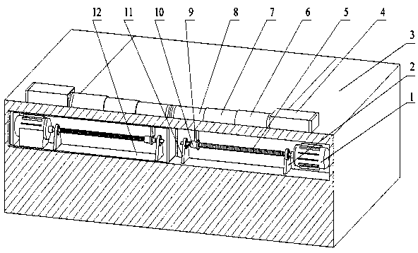
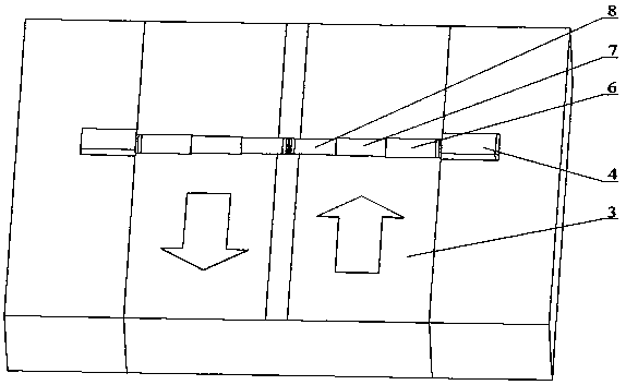
[0015] see figure 1 and figure 2 , the present invention can be divided into two parts, and a part is installed on the road surface 3, comprises three retractable deceleration plates and deceleration belt box 4; 5. The box body 12 is composed of two parts; the two parts are connected by a connecting rod 9 to control the expansion and contraction state of the telescopic speed brake above the road surface 3 . A part on the road surface 3 is left-right symmetrical with the center of the road surface 3, and another part below the road surface 3 is left-right symmetrical with the center of the road surface 3, and the present invention is symmetrical left-right along the transverse direction of the road as a whole.

[0016] The motor 1 is horizontally arranged at the edge of the road below the road surface 3, the output shaft of the motor 1 points to the middle of the road, and the output shaft of the motor 1 is coaxially fixedly connected to one end of the edge of the horizontall...


PUM


Abstract

The invention discloses a telescopic road deceleration strip in road traffic safe equipment. The road surface is provided with a telescopic deceleration plate and a deceleration strip box. The deceleration strip box is located on the edge of the road. A motor is transversely and horizontally arranged on the edge of the road below the road surface. The output shaft of the motor points to the middleof the road and is coaxially and fixedly connected with one end of the edge of a screw rod transversely and horizontally arranged. The middle end of the other end of the screw rod is located in the middle of the road. The screw rod is coaxially sleeved with a screw rod nut. The screw rod nut is fixedly connected with the lower end of a connecting rod. The upper end of the connecting rod extends upwards out of the road surface and is connected with the telescopic deceleration plate. The motor rotates to drive the connecting rod to move transversely and horizontally. The connecting rod can drive the telescopic deceleration plate to enter the deceleration strip box. The telescopic road deceleration strip is exposed out of an original road surface in a contraction state, so that the smoothness is good when the vehicle passes; the service life of the deceleration strip is prolonged; not only can the effect of alarming of an overspeeded vehicle be ensured, but also can unnecessary vibrationand noise be reduced; and the structure is simple and operation is convenient.

Description

technical field [0001] The invention belongs to road traffic safety equipment, and relates to a retractable road deceleration belt that can be laid or removed according to road conditions. Background technique [0002] As a road safety enhancement device, road speed bumps are one of the effective methods for vehicle speed control and play an important role in reducing the incidence of traffic accidents. It warns the driver to consciously and actively reduce the driving speed through two aspects of vision and vibration. The existing road speed bumps are mainly fixed speed bumps, which are fixed after being laid on the ground. The replacement of this kind of fixed speed bumps is complicated, and the fixed speed bumps that have not been replaced for a long time will be damaged to varying degrees due to extrusion and deformation. On the road surface, the rivets used to fix the speed bump are exposed on the road surface, causing damage to the tires of passing vehicles, which in ...

Claims


Application Information

Patent Timeline
Patent Type & Authority Applications(China)
IPC IPC(8): E01F9/529
CPCE01F9/529
Inventor 李仲兴柳亚子江洪贺俊杰唐建
Owner JIANGSU UNIV
Why Eureka
Try Eureka