Centrifugal ventilator for drying hot box

A centrifugal fan and fan technology, applied in the direction of dryer, drying gas arrangement, drying, etc., can solve the problems of inconvenient centrifugal fan operation, inability to rotate left or right, abnormal sound, etc., and achieve structural Simple, convenient operation, and the effect of reducing inertia

Inactive Publication Date: 2018-05-15
JIANGSU HENGKANG ELECTRICAL
View PDF0 Cites 0 Cited by
  • Summary
  • Abstract
  • Description
  • Claims
  • Application Information

AI Technical Summary

Problems solved by technology

The impeller is the main working part that generates wind pressure and transmits energy; the casing is mainly used to introduce gas and discharge gas, and at the same time convert part of the kinetic energy of the gas into pressure energy; the coupling is used to connect the motor and fan to transmit torque; centrifugal Fans are widely used in the ventilation of drying and heating boxes. The existing centrifugal fans for drying and heating boxes have certain disadvantages in use. First, there are often abnormal sounds after starting, and rapid deceleration is easy to cause damage to the motor. Finally, It is also not possible to make the fan rotate left or right, which is inconvenient for the operation of the centrifugal fan, which has a certain impact on people's use. Therefore, we propose a centrifugal fan for drying and heating boxes.

Method used


Image

  • Centrifugal ventilator for drying hot box
  • Centrifugal ventilator for drying hot box
  • Centrifugal ventilator for drying hot box

Examples


Embodiment Construction

[0017] In order to make the technical means, creative features, goals and effects achieved by the present invention easy to understand, the present invention will be further described below in conjunction with specific embodiments.

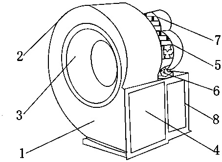
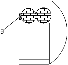
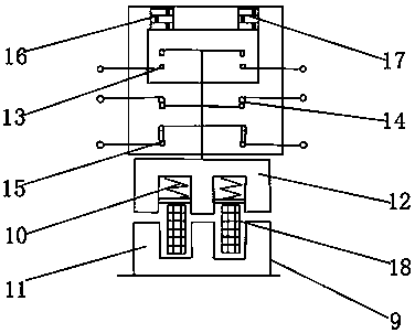
[0018] like Figure 1-5 As shown, a centrifugal fan for drying and heating boxes includes a fan main body 1, an organic casing 2 is fixedly installed on one side of the fan main body 1, and a coupling rod 3 is connected to the middle of the casing 2 for rotation, and the fan main body The lower end of 1 is provided with an air inlet 4 near one side of the casing 2, and the other side of the fan main body 1 is fixedly installed with a motor 5 near the middle of the casing 2, and a speed reducer 7 is fixedly installed on one side of the motor 5, and The lower end of the motor 5 is fixedly equipped with a power interface 6, and the lower surfaces of the motor 5 and the reducer 7 are fixedly installed with a support frame 8, and a contactor 9 is fixed...


PUM


Abstract

The invention discloses a centrifugal ventilator for a drying hot box. The centrifugal ventilator comprises a ventilator main body, a case is fixedly mounted on one side of the ventilator main body, and a shaft coupling rod is rotatably connected to the middle of the case. The position, close to one side of the case, of the lower end of the ventilating main body is provided with an air inlet, a motor is fixedly mounted on the position, close to the middle of the case, of the other side of the ventilating main body, and a reducer is fixedly mounted on one side of the motor. According to the centrifugal ventilator for the drying hot box, a bearing seat, the reducer and a contactor are arranged, an impeller can be fixed, the gaps between the impeller and the two edges of the air inlet are kept to be the same, inexistence of abnormal noise after starting is ensured, the output torque is increased while the motor is decelerated, the load inertia is decreased, damage to the motor due to decelerating is reduced, a draught fan can further made to rotate leftwards or rightwards, operation of the centrifugal ventilator is facilitated, the centrifugal ventilator is suitable for various work environments, and better using prospects are brought.

Description

technical field [0001] The invention relates to the field of centrifugal fans, in particular to a centrifugal fan for drying and heating boxes. Background technique [0002] The centrifugal fan is mainly composed of: impeller, casing, coupling and shaft. The impeller is the main working part that generates wind pressure and transmits energy; the casing is mainly used to introduce gas and discharge gas, and at the same time convert part of the kinetic energy of the gas into pressure energy; the coupling is used to connect the motor and fan to transmit torque; centrifugal Fans are widely used in the ventilation of drying and heating boxes. The existing centrifugal fans for drying and heating boxes have certain disadvantages in use. First, there are often abnormal sounds after starting, and rapid deceleration is easy to cause damage to the motor. Finally, It is not possible to make the fan rotate left or right, which is inconvenient for the operation of the centrifugal fan, wh...

Claims


Application Information

Patent Timeline
Patent Type & Authority Applications(China)
IPC IPC(8): F04D25/08F04D29/056F04D29/00F04D29/66F04D27/00F26B21/00
CPCF04D25/08F04D27/00F04D29/002F04D29/0563F04D29/663F26B21/004
Inventor 孙勇安刘万勤刘正东孙健
Owner JIANGSU HENGKANG ELECTRICAL
Why Eureka
Try Eureka