
Paper bag machine conveying belt adjusting device

A technology of adjusting device and conveyor belt, applied in the direction of conveyor control device, conveyor, conveyor objects, etc., can solve the problems of difficult synchronous start, high cost, poor speed, etc., and achieve fast adjustment, low cost and convenient maintenance. Effect

Pending Publication Date: 2018-05-15
温州巨凯机械有限公司
View PDF9 Cites 1 Cited by
  • Summary
  • Abstract
  • Description
  • Claims
  • Application Information

AI Technical Summary

Problems solved by technology

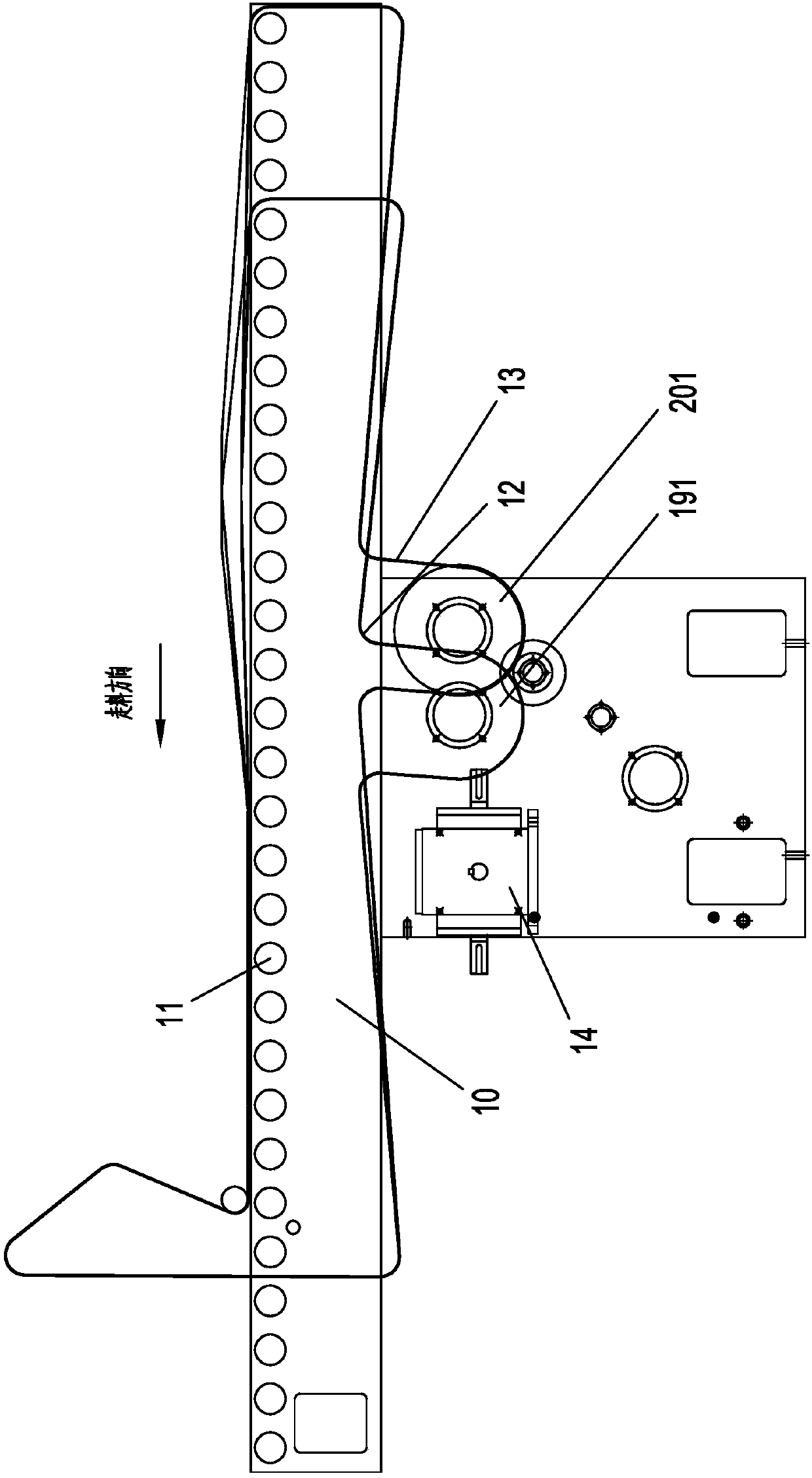
[0002] In the paper bag machine production line, there is a process for folding the bottom of the paper bag. This process is completed during the conveying process of the paper bag, so a conveyor belt is needed to press the paper bag body tightly on the conveying roller for conveying. The side is guided by another conveyor belt to fold the bottom of the bag, so there is a speed difference between the two conveyor belts. In the prior art, two servo motors are used to control the linear speed of the two conveyor belts respectively, so an additional set of control is required. The device controls the speed of the servo motor, which is expensive. At the same time, when the production line starts and stops, there is often a time difference between the servo motor and the power source of other processes in the production line, so it is difficult to start synchronously.

Method used


Image

  • Paper bag machine conveying belt adjusting device
  • Paper bag machine conveying belt adjusting device

Examples


Embodiment Construction

[0021] The specific implementation manners of the present invention will be further described in detail below in conjunction with the accompanying drawings and embodiments. The following examples are used to illustrate the present invention, but are not intended to limit the scope of the present invention.

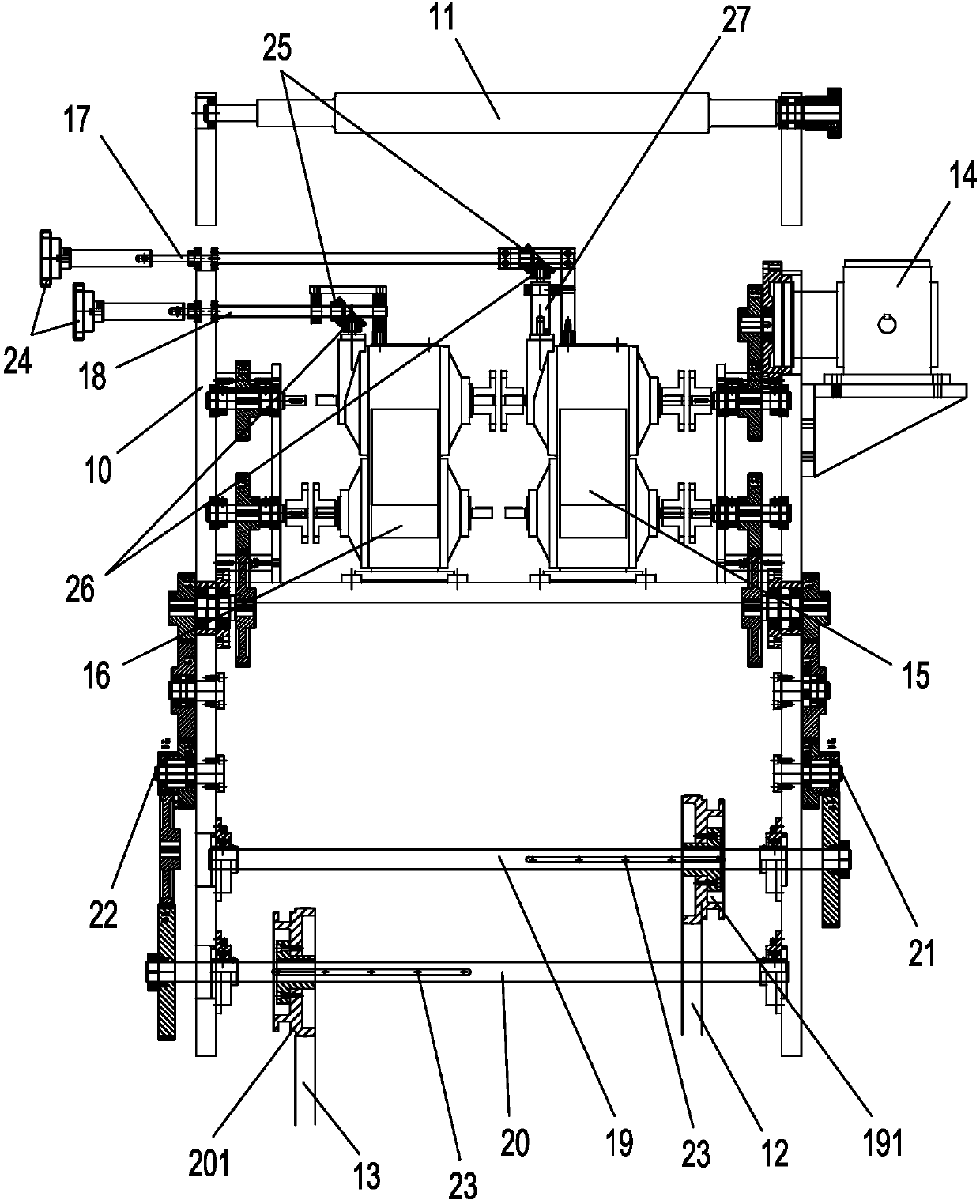
[0022] refer to figure 1 and figure 2 ,Such as figure 1 and figure 2 The conveyor belt adjustment device of a paper bag machine shown includes a frame 10, on which a conveying roller 11 is arranged, and on the frame 10, there are spaced along the axial direction of the conveying roller 11 for The first conveyor belt 12 for conveying the paper bag body and the second conveyor belt 13 for conveying and folding the bottom of the paper bag, the side wall of the frame 10 is provided with a synchronous transmission with the power source of the paper bag (not shown in the figure). The power unit 14, the frame 10 is also provided with a first stepless speed governor 15 and a...


PUM


Abstract

The invention provides a paper bag machine conveying belt adjusting device. The paper bag machine conveying belt adjusting device comprises a rack. The rack is provided with a conveying roller. The rack is further provided with a first conveying belt and a second conveying belt which are arranged in the axial direction of the conveying roller in a spaced manner, the first conveying belt is used for conveying a paper bag body, and the second conveying belt is used for conveying and folding the paper bag bottom. The side wall of the rack is provided with a power part which is in synchronous transmission with a paper bag machine power source. The rack is further provided with a first stepless speed adjustor and a second stepless speed adjustor. One end of an input shaft of the first steplessspeed adjustor is connected with the power part, and the other end of the input shaft of the first stepless speed adjustor is connected with an input shaft of the second stepless speed adjustor. An output shaft of the first stepless speed adjustor is used for driving the first conveying belt, and an output shaft of the second stepless speed adjustor is used for driving the second conveying belt. The rack is further provided with a first adjusting shaft for adjusting the transmission ratio of the first stepless speed adjustor and a second adjusting shaft for adjusting the transmission ratio ofthe second stepless speed adjustor. The paper bag machine conveying belt adjusting device has the beneficial effects that speed adjustment is convenient, the production cost is low, and maintenance isconvenient.

Description

technical field [0001] The invention relates to the field of paper bag machines, in particular to a conveyor belt adjusting device for paper bag machines. Background technique [0002] In the paper bag machine production line, there is a process for folding the bottom of the paper bag. This process is completed during the conveying process of the paper bag, so a conveyor belt is needed to press the paper bag body tightly on the conveying roller for conveying. The side is guided by another conveyor belt to turn over the bottom of the bag, so there is a speed difference between the two conveyor belts. In the prior art, two servo motors are used to control the linear speed of the two conveyor belts respectively, so an additional set of control is required. The device controls the speed of the servo motor, which is costly. At the same time, when the production line starts and stops, there is often a time difference between the servo motor and the power source of other processes ...

Claims


Application Information

Patent Timeline
Patent Type & Authority Applications(China)
IPC IPC(8): B65G23/04B65G23/30B65G15/22B65G43/00B31B70/04B31B70/26
CPCB65G15/22B65G23/04B65G23/30B65G43/00B65G2203/0291B65G2201/0238
Inventor 蔡锦丹刘德明朱伯乐
Owner 温州巨凯机械有限公司
Learn More