Wind energy installation and method for controlling the cooling of a wind energy installation

一种风能设备、冷却单元的技术,应用在机械设备、风能发电、安装/支撑风力发动机的配置等方向,能够解决不安全、提高系统成本、不适用近海的使用等问题,达到成本低的效果

Active Publication Date: 2020-03-31
WOBBEN PROPERTIES GMBH
View PDF17 Cites 0 Cited by
  • Summary
  • Abstract
  • Description
  • Claims
  • Application Information

AI Technical Summary

Problems solved by technology

[0012] Some previously known solutions are also partly cost-intensive (for example the solutions known from DE 10 2004 061 391 or EP2 203 642) and the solutions known from DE 10 2009 055 784 are also not suitable for offshore usage of
[0013] Finally, the previously known solutions are very maintenance-intensive, which also increases the cost for the system
Most of the previously known solutions are not yet retrofittable in existing installations and some solutions, such as the one known from EP 1 798 414, are aimed at the destruction of cooling fins mounted on the outer wall of the tower, i.e. deliberate is not safe for damage to
[0014] In particular, the solutions known from EP 1 798 414, DE 10 2009 055784, EP 2 002 120 or DE 10 2004 061391 do not meet the requirements for an attractive aesthetic of the entire wind energy installation

Method used


Image

  • Wind energy installation and method for controlling the cooling of a wind energy installation
  • Wind energy installation and method for controlling the cooling of a wind energy installation
  • Wind energy installation and method for controlling the cooling of a wind energy installation

Examples


Embodiment Construction

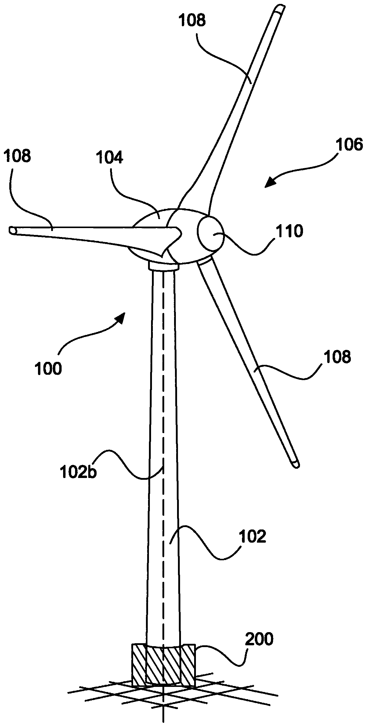
[0040] figure 1 A schematic diagram of a wind energy installation according to the invention is shown. The wind energy installation 100 has a tower 102 with a longitudinal axis 102 b and a pod 104 on the tower 102 . Tower 102 can have a plurality of tower segments which are placed one above the other in order to form tower 102 . An aerodynamic rotor 106 having, for example, three rotor blades 108 and a spinner 101 is arranged on the pod 104 . During operation of the wind energy plant, the aerodynamic rotor 106 is set in a rotational motion by the wind and thus also rotates the rotor rotor part of the generator, which is directly or indirectly coupled to the aerodynamic rotor 106 . A generator is provided in the pod 104 and generates electrical power. The pitch angle of the rotor blade 108 can be varied by a pitch motor at the rotor blade root of the respective rotor blade 108 .

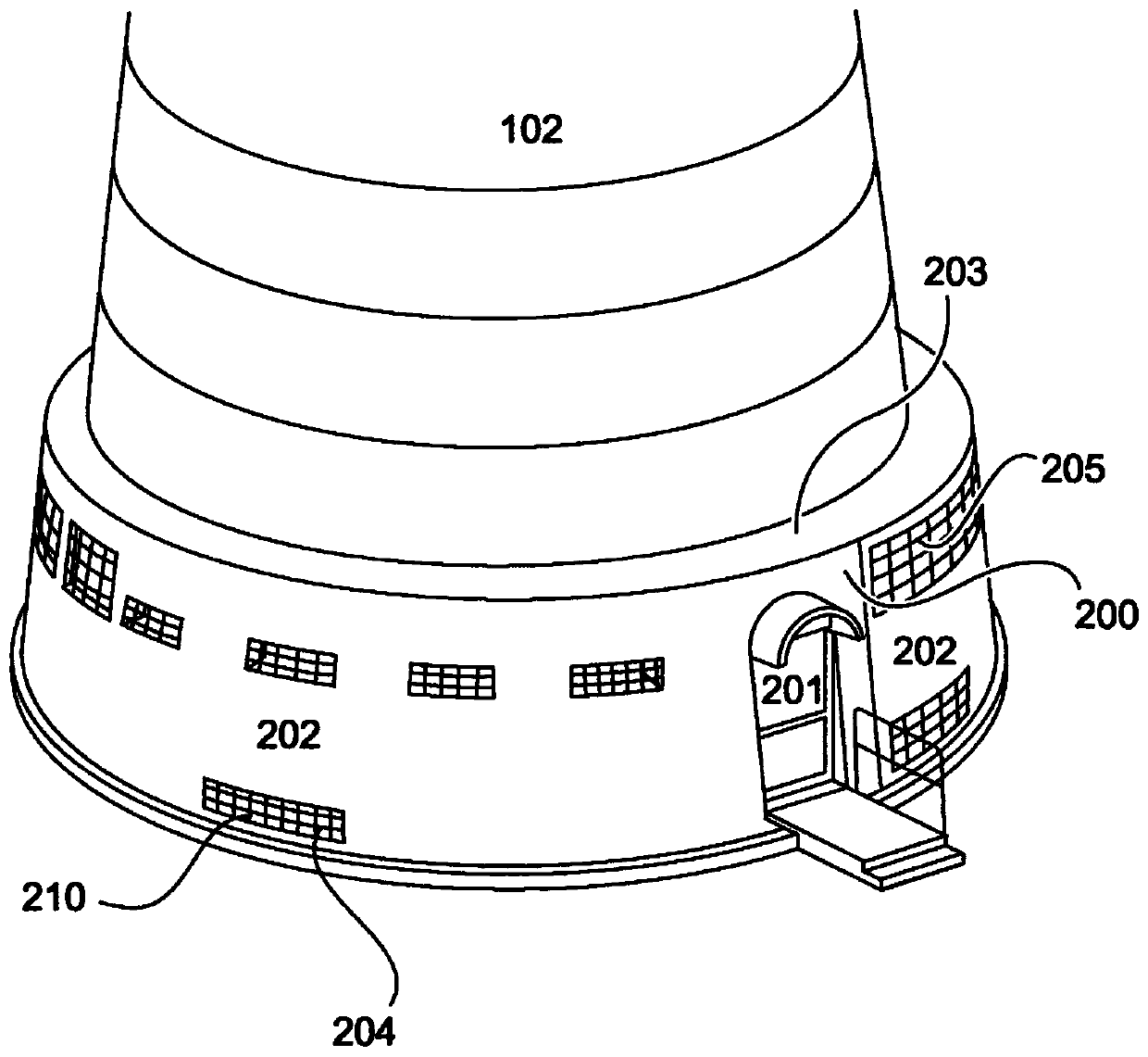
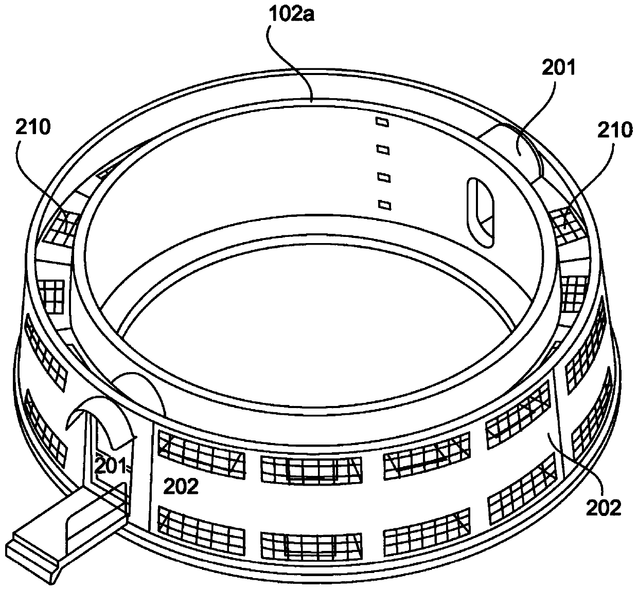
[0041] A first cooling unit 200 is provided in the region of the lower tower section. The fir...


PUM


Abstract

A wind energy installation is proposed in which the lines through which the cooling medium flows are led outwards from the interior of the wind energy installation through the tower wall or through the base, and the cooling lines in the heat exchanger are routed from the outside It rests on the tower or is arranged there and between the tower wall and the cover of the wall of the cooling system.

Description

technical field [0001] The invention relates to a wind energy installation and a method for controlling the cooling of a wind energy installation. Background technique [0002] When converting the energy in a wind energy installation, losses in the form of heat usually occur. This applies not only when the kinetic energy of the wind is converted into electrical energy in the generator of the wind energy installation, where the losses usually occur in the main drive train of the wind energy installation, but also when the energy generated by the wind energy installation is electrically fed into the network, Also applies, for example, when feeding into a medium-voltage network. For this, power electronics such as inverters, transformers and / or power distribution equipment etc. are usually required. [0003] In wind energy installations, the main drive train is installed in the nacelle of the wind energy installation, where it is customary in the transmission (when such a tra...

Claims


Application Information

Patent Timeline
Patent Type & Authority Patents(China)
IPC IPC(8): F03D80/60F03D13/20
CPCF05B2260/20F03D13/20F03D80/60Y02E10/728Y02B10/30F03D13/22F05B2260/201Y02E10/72
Inventor 扬·德弗里斯卡伊·恩斯科纳图斯马尔特·克尼茨
Owner WOBBEN PROPERTIES GMBH
Why Eureka
Try Eureka