
Double-room ventilation device

A ventilation device and air inlet technology, which is applied in ventilation system, space heating and ventilation, space heating and ventilation control input, etc. It can solve the problems of limited natural ventilation, low ventilation efficiency, and large electric energy load. , to achieve the effects of saving energy consumption and cost input, improving the quality of life, and being easy to cover up

Inactive Publication Date: 2018-05-08
FOSHAN CHUANDONG MAGNETOELECTRICITY
View PDF6 Cites 0 Cited by
  • Summary
  • Abstract
  • Description
  • Claims
  • Application Information

AI Technical Summary

Problems solved by technology

The most commonly used method of ventilation is natural ventilation by opening windows. However, natural ventilation is more restricted and less efficient. Therefore, air conditioners, forced convection and air purifiers are more common.
Among them, most of the existing ventilating fans are fixedly installed on the wall, and a ventilation hole is opened on the wall to form an air duct, which is driven by the ventilating fan to generate indoor and outdoor convection. The damage of the air conditioner is relatively serious, so it generally cannot meet the actual needs; while the energy consumption of the air conditioner is relatively large, and it is difficult to adapt to the daily use of ventilation due to the large electric energy load; the air purifier needs to replace the filter frequently, and the replacement The gas efficiency is not high, and the existing ventilation methods are mostly used by manual control, which is difficult to meet the development needs of modern smart home systems

Method used


Image

  • Double-room ventilation device

Examples


Embodiment Construction

[0015] The technical solutions of the present invention will be described below in conjunction with the accompanying drawings and embodiments.

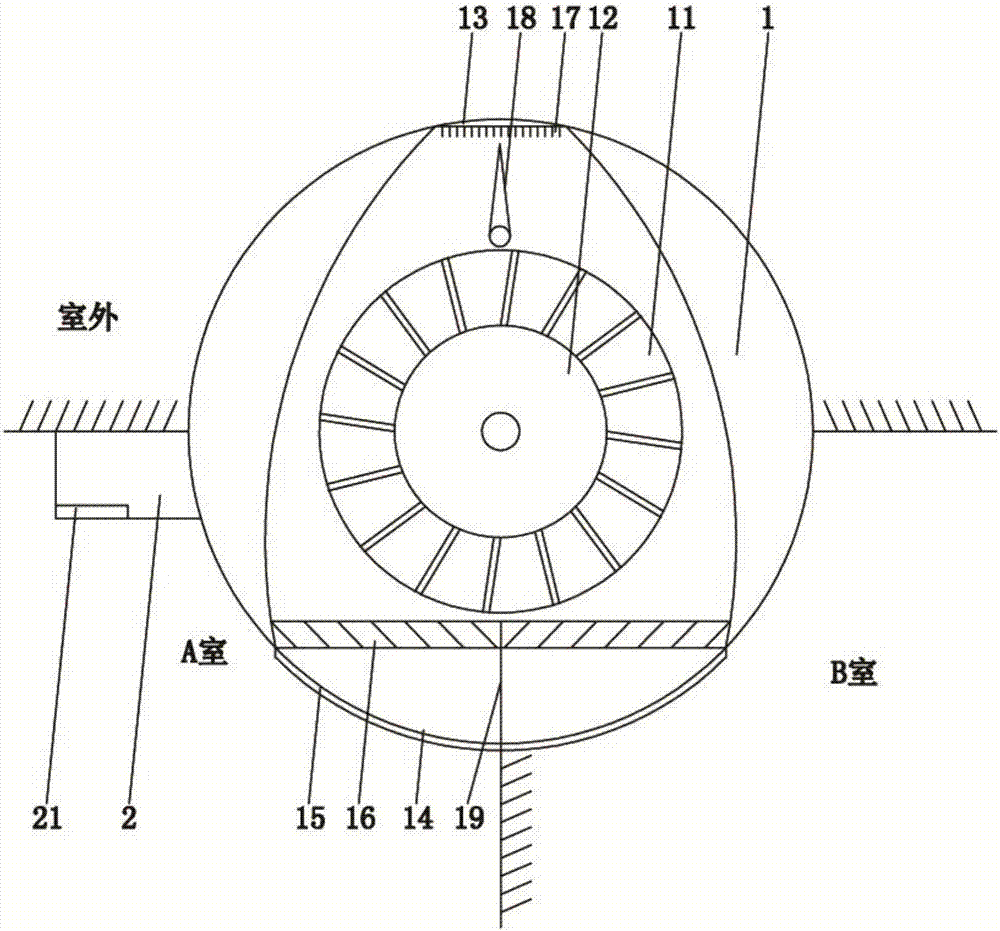
[0016] Such as figure 1 As shown, a double-chamber ventilation device according to the present invention includes a hollow housing 1 and a controller 2. The housing 1 is provided with an impeller 11 and a motor 12 that drives the rotation of the impeller 11. The housing 1 is circular Arranged in a barrel-shaped structure, the housing 1 is buried on the partition wall of two adjacent rooms, and part of the outer edge of the housing 1 is pierced on the outer wall of the room; the outer side wall of the housing 1 is provided with an air outlet 13. There are two air inlets 14 on the inner side wall of the housing 1, and the two air inlets 14 are respectively connected to the corresponding rooms. Movable cover plate 15, the controller 2 is electrically connected with the motor 12, the controller 2 is fixed on the wall of one of the rooms,...


PUM


Abstract

The invention relates to the technical field of a ventilation and air interchange device, in particular to a double-room ventilation device. The double-room ventilation device comprises a hollow shelland a controller. An impeller and a motor used for driving the impeller to rotate are arranged in the shell, and the shell is in a cylindrical structure and is buried on a division wall of two adjacent rooms. An air outlet is formed in the outer side wall of the shell, and two air inlets are formed in the inner side wall of the shell and respectively communicate with the corresponding rooms. A division plate is arranged in the middle of the place between the two air inlets, and movable cover plates are arranged on the air inlets. The double-room ventilation device has a reasonable structure and meets he ventilation requirements of the two rooms. Two independent air flues are established in the inner chamber of the shell through a rudder piece and the division plate. One air inlet is opened, so that the ventilation and air interchange requirements of the corresponding rooms can be realized. The energy consumption and cost input can be saved, and convenient switch and flexible use are realized. The quality of indoor air is monitored in time through the controller and is displayed through a display screen, and the quality of life of a user can be effectively improved.

Description

technical field [0001] The invention relates to the technical field of ventilation devices, in particular to a double-chamber ventilation device. Background technique [0002] With the development of society, people's material and cultural living standards have been significantly improved, and people are paying more and more attention to indoor air quality. Indoor air quality factors include air humidity, temperature, dust particles and other harmful gases. The easiest and most effective way to improve indoor air quality is ventilation. The most commonly used ventilation method is to open windows for natural ventilation. However, natural ventilation is more restricted and less efficient. Therefore, air conditioners, forced convection with ventilation fans, and air purifiers are more common. Among them, most of the existing ventilating fans are fixedly installed on the wall, and a ventilation hole is formed on the wall to form an air duct, which is driven by the ventilating ...

Claims


Application Information

Patent Timeline
IPC IPC(8): F24F7/007F24F11/52F24F110/20F24F110/50
CPCF24F7/007
Inventor 龙克文颜天宝
Owner FOSHAN CHUANDONG MAGNETOELECTRICITY
Learn More