Combined type soot removal arrangement structure and arrangement method for waste incineration boiler

A technology of waste incineration and layout structure, which is applied in the direction of combustion method, incinerator, combustion type, etc., and can solve the problems of frequent fluctuation and instability of operating conditions and output load

Pending Publication Date: 2018-05-08
SHANGHAI SUS ENVIRONMENT
View PDF8 Cites 3 Cited by
  • Summary
  • Abstract
  • Description
  • Claims
  • Application Information

AI Technical Summary

Problems solved by technology

[0002] As we all know, due to the particularity of fuel, compared with conventional coal-fired power plant boilers

Method used


Image

  • Combined type soot removal arrangement structure and arrangement method for waste incineration boiler
  • Combined type soot removal arrangement structure and arrangement method for waste incineration boiler

Examples


Embodiment Construction

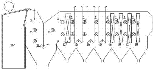
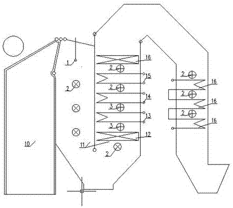
[0017] Compared with the conventional coal-fired power plant boiler, the waste incineration boiler has a simple structure, and the main components (according to the flue gas flow direction) include: a flue 10 of the waste incineration boiler, a water wall flue 11, a primary evaporator 12, and a low-temperature superheater 13. Medium-temperature superheater 14, high-temperature superheater 15, secondary evaporator 16, economizer 17, etc. Among them, the flue 10 of the waste incineration boiler is to prevent the scour and corrosion of high-temperature flue gas, and SiC wear-resistant and corrosion-resistant castables are poured in the furnace.

[0018] For horizontal boilers, the second and third flues (water-cooled wall flue 11) are cavity flues composed of water-cooled membrane walls, and no other heating surface components are placed inside, and no wear-resistant and corrosion-resistant pouring is made on the flue walls. Castable, suitable for installing furnace wall soot blo...


PUM


Abstract

The invention relates to the field of waste incineration, in particular to an arrangement structure and arrangement method for a soot removal device suitable for a waste incineration boiler. Accordingto the arrangement structure and arrangement method, the waste incineration boiler is divided into different areas according to the medium temperature of each heating surface of the waste incineration boiler, the temperature of flue gas flowing through the heating surfaces and the factors of forming coking soot deposition, and soot removal devices with a reasonable types are arranged in the areas; and the areas are characterized in that a boiler wall soot blower and a pulse shock wave soot blower are arranged in a cavity flue formed by a water cooling wall, a pulse shock wave soot blower is additionally arranged at the evaporation heating surface with the flue gas temperature of 600 DEG C or more and is arranged at the front part of a superheater, a steam soot blower is additionally arranged on the heating surface of the superheater with the flue gas temperature of 400 DEG C or more, and a pulse shock wave soot blower is additionally arranged on the convection heating surface with theflue gas temperature of 400 DEG C or less and is arranged at the rear part of the superheater.

Description

technical field [0001] The invention relates to the field of garbage incineration, and relates to an arrangement structure and an arrangement method of an ash cleaning device suitable for a garbage incineration boiler. Background technique [0002] As we all know, due to the particularity of fuel, compared with conventional coal-fired power plant boilers, the operating conditions and output load of waste incineration boilers fluctuate frequently and are very unstable. In order to ensure the normal operation of the waste incineration boiler, prevent the low efficiency of the heat exchange surface caused by the coking and ash accumulation on the heating surface, affect the output of the boiler, and reduce the occurrence of situations such as the flue being blocked by ash accumulation and being forced to shut down the boiler, the boiler During operation, it is a very necessary maintenance measure to regularly clean the dust of each group of heating surfaces of the waste inciner...

Claims


Application Information

Patent Timeline
IPC IPC(8): F23G5/44F23J3/02
CPCF23G5/44F23J3/02
Inventor 黄洁彭小龙白力严梦帆王刚谢军张宏泽王若飞张琳琳沈咏烈
Owner SHANGHAI SUS ENVIRONMENT
Why Eureka
Try Eureka